Quantcast
Channel: Linear Motion Tips
Viewing all 203 articles
Browse latest View live
↧

What are differential roller screws and how do they differ from planetary designs?

$
0
0

Traditional roller screws — sometimes referred to as planetary roller screws — can produce axial forces comparable to hydraulic cylinders, with the speed and precision capabilities of ball screws, at a price point that falls between the two. A variation of the planetary roller screw — referred to as a differential roller screw — reduces some of the complexity of the planetary design, without sacrificing load and speed capacity, and does so at a price point closer to that of a ball screw.

Traditional planetary roller screws rely on threaded rollers, referred to as planets, to transmit forces between the screw shaft and the nut. The rollers, screw shaft, and nut inner diameter have the same lead, so each rotation of the screw moves the nut a linear distance equal to the lead of the screw. (In screw terminology, the lead is the linear distance traveled per full rotation of the screw shaft.) The ends of the rollers, or planets, mesh with geared rings on each end of the nut, allowing the rollers to act like planets, spinning on their axes while revolving around the screw shaft.

Roller screw actuator

In a traditional planetary roller screw, the rollers, screw shaft, and nut inner diameter all have the same lead, so with each revolution of the screw, the nut moves a linear distance equal to the lead of the screw.
Image credit: Rollvis SA

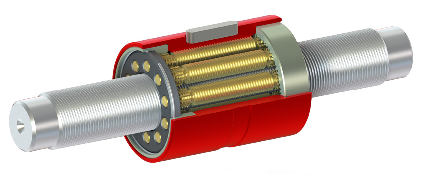
Differential roller screws are very similar to planetary roller screws, consisting of a threaded screw shaft, threaded rollers, and a nut. However, for a differential roller screw, the inner diameter of the nut does not have a lead (threads). Instead, it has grooves at each end. The rollers also differ from those used in planetary design. Instead of a constant pitch diameter, rollers for differential screws have a varying pitch diameter — larger in the middle, where the roller engages with the screw shaft, and smaller on the ends, where the roller engages with the grooves of the nut. This variance in pitch diameter between the roller-screw engagement and the roller-nut engagement means the nut travels at a different rate than the screw, hence the term “differential” roller screw.

differential roller screws

In a differential roller screw, the rollers have a larger pitch diameter in the middle, and the nut has only grooves (no threads). Because the pitch diameter of the roller-screw interface is different than the pitch diameter of the roller-nut interface, the speed of the nut differs from the speed of the screw – hence, the term “differential roller screw.”
Image credit: Scheaffler


Differential roller screws can be thought of as planetary roller screws with “built-in” gearing.


Although the nut inner diameter isn’t threaded, the large contact area (more contact points, with line contact) between the screw shaft and the rollers gives differential roller screw assemblies high load capacity. And their design is simpler and easier to manufacture than that of a planetary roller screw, so differential roller screws can be offered at a lower price point than planetary designs. However, this design also makes them subject to slipping, so position feedback is typically recommended for applications that use differential roller screws.

The post What are differential roller screws and how do they differ from planetary designs? appeared first on Linear Motion Tips.

↧

XY2Z-theta motion system improves wafer inspection for the semiconductor industry

$
0
0

For more than fifty years, the Dutch linear-motion company PM has developed and produced precision linear and rotating bearings and slides. It focuses on applications requiring smoothness and stiffness from their linear bearings 
 and continues to expand its standard range of linear components. But customization is becoming the norm — and now, catalog products account for only around 30% of sales. Customization usually begins with the machine builder asking for slight changes to some standard component — for just a bit more precision or a smaller footprint or an additional mounting option, for example. 30% of PM’s business is here.

The Vega semiconductor backend inspection machine  owes its high accuracy to the fact that all centers of gravity and driving forces go through one plane. PM engineers used their linear-bearing expertise and knowledge from the production floor to perfect the motion system.

The final third of PM’s business is in supplying ultra-precise positioning solutions. That’s in part because very few end users consider such designs to be their core competency. Here, PM collaborates with customers to build motion systems 
 and continually works towards projecting the design features likely to be required by industry over the next five years. One design to come of the latter efforts is called the Vega motion stage 
 a key subsystem in the manufacturer’s XY2Z-theta motion system for backend wafer inspection applications.

“The semiconductor industry is very demanding,” says PM manager of R&D and engineering Jan Willem Ridderinkhof. “So our logic is that if we can perform in that industry, we should also be able to satisfy the medical market.”

High semiconductor throughput generates a lot of heat

Over a stroke of more than three hundred millimeters, mechanical accuracy in the X and Y directions must be better than 1 ”m at accelerations of 2 g and speeds to 2 m/sec. Vibrations in that plane must remain below 25 nm. Vibrations in the Z axis — used to get the wafer into the optics’ focal point — must stay below 10 nm. Complicating matters is that the wafer must shoot back and forth at lightning speed 
 a motion that generates copious heat in the process. But such motion is essential to maintaining the high throughput required for effective chip production.

“Our starting design philosophy was that all centers of gravity and driving forces should go through one plane,” says PM lead engineer Mathys te Wierik. “To illustrate why, recall that a motorcycle on the highway applies force to the asphalt — and the bike’s center of gravity and that of the rider are stacked. But opening the throttle on the motorcycle can induce a wheelie” which takes those centers of gravity out of their common plane.”

Designing was a very iterative process, because every part that one remove or add has a direct effect on the center of gravity.

In a system such as the Vega, such physics can seriously degrade design accuracy. “Our motors can’t cause an angular momentum — so we align the assembly’s centers of gravity and motor forces. An added benefit is less load on the bearings 
 which in turn extends system life.”

it’s more complex than it sounds. For only the X direction, it is still relatively easy to let the motor drive through the center of gravity. “Normally we’d put a second module on top to realize the movement in the other direction 
 and a third module for the Z axis,” explains te Wierik. “But stacking like this alters the moving part’s center of gravity — which is an unwanted effect 
 because then the masses effectively get a lever arm, which in turn degrades overall system stiffness.”

Several engineering iterations yielded a construction with a horizontal frame that runs over two bearings — much like a train on rails. In that square frame, there’s a platform that glides vertically back and forth. PM integrated the Z-theta module in this sliding structure, which is responsible for rotations and up and down movements 
 so all the masses stay in a common plane.

The Z-theta module ensures that the wafer is properly positioned under the optics.

Iterative process for the motion-stage development

The next design element was determining a suitable shape of the frame to maximize stiffness while minimizing bending and mass using PM’s own topology optimization software written in MATLAB. Maintaining manufacturability meant keeping the profiles constant lengthwise for easier milling. Eventually the design took a C-shaped profile to let the panel for the Y movement slide in the channel.

Next came various designs for driving the key axis. Ultimately, the engineers chose an ironless linear motor. “That complicates construction but lets us mount the motor, bearing, and encoder all underneath the C profile,” says te Wierik. With that component subject to the toughest design requirements, the rest of the machine is belt with less accuracy and more cost-effectively.

“Every piece of materixal machined or added to the machine directly affects the center of gravity 
 and all objects put on the stage also have masses mass for which we must account. That is why we have chosen to focus on backend inspection. After all, a wafer has a well-defined mass,” adds Ridderinkhof.

Another challenge was thermal management — especially because the machine’s frame is aluminum.

“Aluminum is light and relatively stiff so very suitable for fast-moving systems 
 but aluminum has a high thermal expansion coefficient,” explains te Wierik. “Our extensive calculations and simulations revealed ways to sufficiently dissipate heat and keep the expansion under control. The solution of cooling fins required added mass, but was the best solution.”

Information for this article provided by Alexander Pil, Techwatch editor for PM. For more information, visit www.PM.nl.

The post XY2Z-theta motion system improves wafer inspection for the semiconductor industry appeared first on Linear Motion Tips.

↧
↧

What are some alternatives to L10 bearing life?

$
0
0

If you work with linear ball or roller bearings, you’re familiar with the L10 bearing life equation, which states that bearing life is equal to the bearing’s rated dynamic load capacity, divided by the applied load, raised to a power of 3 (for ball elements) or 10/3 (for roller elements).

Introduced in 1947 by Gustaf Lundberg and Arvid Palmgren, based on work done at SKF, the bearing life equation represented a significant development in the selection and application of bearings. Prior to the adoption of the Lundberg-Palmgren equation, each manufacturer used its own method to determine bearing life, making comparisons between products difficult, if not impossible. The Lundberg-Palmgren equation represented a significant advancement for the bearing industry, and to this day serves as the foundation of bearing sizing and selection.


In the original paper by Lundberg and Palmgren, the load/life exponents (p) used in the bearing life equation were given as “3” for ball bearings and “4” for roller bearings with pure line contact. However, because the rollers used in bearing applications don’t experience pure line contact with the bearing raceway under some loads, the authors revised the exponent used in the roller bearing equation from “4” to “10/3” in 1952, and this version of the formula is still used today.


The L10 bearing life introduced by Lundberg and Palmgren specifies the distance (or number of revolutions, for radial bearings) that 90% of identical bearings, operating under identical conditions, can travel before fatigue (spalling or flaking) occurs on the rolling elements or raceways.

Spalling on the raceway of a bearing.

But in some industries and applications, a reliability greater than 90% is required, especially if the bearing performs a mission-critical function whose failure could result in physical harm to people or loss of an entire system. Case in point: If you’ve ever worked on an application in the aerospace, medical, pharmaceutical, or transport industry, you’ve probably been tasked with selecting a bearing that has 95%, 99%, or even higher reliability.

Fortunately, the most recent version of the ISO standard that deals with bearing life calculations — ISO 281:2007, Rolling bearings – dynamic load ratings and rating life — addresses the need for bearing life reliabilities higher than 90%. The standard now includes a list of factors, denoted a1, that provide adjustments to the bearing life to reflect reliabilities ranging from 95% to 99.95%.

L10 bearing life


Notice that in this discussion we’ve referenced the ISO 281:2007 standard, which addresses rolling bearings. But if you’ve read some of our other articles on bearing life, you might recall that the dynamic load ratings and life for linear rolling bearings are specified in the ISO 14728-1:2017 standard. We refer to ISO 281:2007 in this article because ISO 14728-1:2017 references the ISO 281:2007 standard for life calculations.


For example, if a linear bearing application requires a reliability of 98% (referred to as L2m life, since it implies that only 2% of bearings are statistically likely to fail), simply multiply the calculated L10 life by 0.37, which is the adjustment factor (a1) for 98% reliability. This gives the distance the bearing will travel with 98% certainty before fatigue occurs.

For a linear ball bearing (p = 3) with an applied load (F) of 1000 N and a load capacity (C) of 1320 N, the L2m life (98% reliability) will be:

L10 bearing life

L10 bearing life

Similarly, to determine the required dynamic load capacity that will allow a linear ball bearing with a 1000 N load to travel 85,000 km, with 98% reliability, the equation can be rearranged as:

L10 bearing life

Regardless of the calculated reliability, it’s important to remember that the bearing life equation assumes bearings are “made with contemporary, commonly used, high quality hardened bearing steel in accordance with good manufacturing practice,” and that the group of bearings are identical and operate under the same conditions.

In other words, bearing life is a theoretical calculation based on probabilities of failure. Calculating bearing life with a higher reliability does not mean that a bearing won’t fail before it reaches the specified travel, but it does reduce the probability of bearing failure.


Controversy in the world of bearing life calculations

Anyone who has worked with radial or linear rolling bearings has probably used the bearing life equation so often that they can recite it in their sleep. But it turns out that this ground-breaking equation — introduced nearly 70 years ago and used by virtually every design engineer in the world — has a history of controversy that exists to this day. A key point of contention regarding bearing life is whether bearing steel actually has a fatigue stress limit — a point of loading under which no material fatigue would occur (assuming elastohydrodynamic lubrication is present between the bearing surfaces).

The most recent ISO standard, ISO 281:2007, incorporates a life adjustment factor (denoted aISO) that includes a fatigue stress limit, but some engineers and researchers argue that there is no evidence for a fatigue limit in bearing steels. In 2010, the Society of Tribologists and Lubrication Engineers (STLE) published an article explaining the evolution of bearing life calculations and how the new ISO 281:2007 standard came to be. One of the issues addressed in the article is the inclusion of the fatigue stress limit. One month later, STLE published a rebuttal to the new ISO standard and its use of the fatigue stress limit, written by Erwin Zaretsky, a distinguished research associate at the NASA Glenn Research Center in Cleveland and a well-respected engineer in the bearing community.

Reading these two articles, I found it interesting that something most of us in the engineering world take for granted — the probability of failure of a bearing under a given load — is still difficult to accurately quantify and whose further development and refinement is being driven by two conflicting theories. Even with incredible advances in material science, testing, and calculation methods, we really don’t know exactly how bearing elements (balls, rollers, and raceways) behave under the extreme loads, pressures, speeds, and lubrication conditions they encounter in even “normal” applications.

If you’re interested in the history of the L10 bearing life equation and the ongoing discussions around its advancement, I highly recommend reading the two articles from STLE.

The post What are some alternatives to L10 bearing life? appeared first on Linear Motion Tips.

↧

How to reduce the effects of stiction (stick-slip) in linear guides

$
0
0

Unless you’re playing the violin, stiction, or stick-slip, is an unwanted condition caused by the difference between static and dynamic friction between the two surfaces. When stiction occurs in linear guides, it can lead to chattering (“jerky” motion), seized motion, fluctuating torque requirements, or a loss of accuracy in the form of overshooting.

What causes stiction?

The coefficient of static friction (Όs) between two surfaces is almost always higher than the coefficient of dynamic (kinetic) friction (Όk), and this variation in friction is the underlying cause for stick-slip.

All surfaces have some amount of roughness. Even highly finished and polished surfaces are not perfectly smooth — they have peaks (referred to as “asperities”) and valleys that reduce the effective contact area of the surfaces. In other words, in some places, only the peaks of the two surfaces are in contact, while in other places, the peaks of one surface settle into the valleys of the other surface. And in some places, there is no contact between the surfaces.

stiction

Linear bearing surfaces are microscopically rough, with asperities and valleys, so the real contact area between them is much smaller than the apparent contact area.

Because the individual contact areas are very small, the pressure between the surfaces is extremely high (pressure = force ÷ area), and adhesion occurs at these points through a process known as cold welding.

Before the surfaces can move, the bonds that cause this adhesion must be broken. Similarly, where the surfaces interlock (the peaks of one surface settle into the valleys of the other surface), abrasion, or plastic deformation, must occur to break these interlocked areas and allow the surfaces to move.

Once the motive force is high enough to break these bonds between the surfaces — and overcome the static friction — motion begins. But even during motion, some abrasion still occurs because the surfaces are still not perfectly smooth. The resistance to motion due to the remaining surface roughness is referred to as dynamic, or kinetic, friction.

How to reduce stiction

For linear bearings that use lubrication (virtually all recirculating bearings and some plain bearings), the movement between the bearing surfaces draws lubrication into the microscopic spaces between the surfaces. As the relative velocity of the surfaces increases, the lubrication film becomes thicker and surface-to-surface contact is reduced, so friction between the surfaces decreases.

But linear bearings travel a finite distance and then return in the opposite direction (as opposed to radial bearings, which can rotate in the same direction indefinitely), so they spend a good amount of time in what is known as mixed lubrication, where friction is determined by both the properties of the surfaces and the properties of the lubricant. Therefore, proper lubrication is the best way to control or reduce the effects of stiction in recirculating bearings (and in some plain bearings).

stick-slip

Bearings operate under one of three lubrication conditions. In mixed lubrication, friction is influenced by both surface properties and the properties of the lubricant.
Image credit: nature.com

Stick-slip, or stiction, is often more problematic in plain bearings than in recirculating bearings. This is because plain bearings experience a greater difference between static and dynamic friction coefficients. And the friction coefficient of a plain bearing can vary, depending on the applied load, wear, and environmental factors.

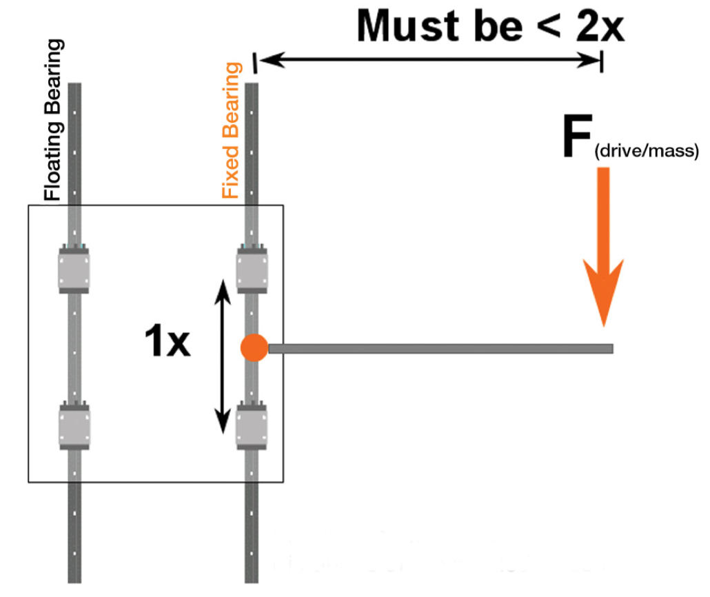
For plain bearings that ride on round shafts, one way to counter the effects of stick-slip is to choose shafts with the highest surface finish (lowest surface roughness) that is practical. And following the 2:1 ratio (also referred to as the 2:1 rule or the binding ratio) — which specifies that the moment arm distance should not be more than twice the bearing length — is very often necessary to prevent stick-slip in plain bearing applications.

plain bearings

For plain bearings, the 2:1 ratio specifies that the moment arm created by the driving force or applied load should be less than two times the center-to-center distance between bearings.
Image credit: igus

Another option to minimize, or even prevent, stick-slip is to use air bearing guides. For air bearings, friction is solely a function of air shear from motion. Therefore, the difference between static and kinetic friction in an air bearing assembly is essentially zero, so the problem of stick-slip is virtually eliminated.

The post How to reduce the effects of stiction (stick-slip) in linear guides appeared first on Linear Motion Tips.

↧

Linear guides, power transmission, actuators see unexpected applications

$
0
0

Our 2020 survey of the industry indicates an unabated trend towards more automation of previously static or manually tended systems. Key to these new offerings is installation simplicity for OEMs and end users of linear components for linear axes 
 as well as positioning stages and Cartesian robots.

In fact, Cartesian robots (also called linear robots) increasingly serve as turnkey solutions where tasks were previously done manually. That’s in part because (where suitable) linear-based solutions offer simplicity and precision at a price point that’s unrivaled by other solutions. So linear-motion adherents want these multi-axis arrangements to come to mind when laypeople and engineers alike discuss robotics.

“When discussing robotics, some people think of walking robots. Others picture consumer-grade designs or even toys and Japanese companion robots. Those in automation often conjure a 6-DOF robot or SCARA in their mind’s eye. I’d really like to change such preconceived notions — at least in our industry. After all, a gantry qualifies as a robot. It is taking human motion and it’s repeating it and it’s programmable,” says Macron Dynamics national sales manager Michael G. Giunta.

Giunta considers it a core mission to help industry recognize Cartesian arrangements as robotics.

“The official definition of robot is a machine capable of automatically replicating certain human motions and functions. So a linear-motion installation in a fast-food kitchen that picks up a fryer basket and moves it to a second location as a human would do is in fact a robot. In contrast, the Da Vinci surgical system is often called a robot, but technically it does not qualify — because its movements are ultimately controlled by a human being,” explains Giunta.

These are IMA-S integrated electric servo actuators from Tolomatic that meet hygienic standards with no harborage points for bacterial growth. 316 stainless-steel construction resists corrosion and withstands hot and high-pressure caustic washdown. IP69K ingress protection makes these linear actuators suitable for open machine designs. A hollow-rotor motor design outputs up to 11.1 kN and strokes to 450 mm with options for planetary roller screws or ballscrews. Feedback is via a multi-turn absolute encoder (Hiperface DSL, Hiperface Sin-Cos, EnDat 2.2), incremental encoder, or resolver to integrate with most PLCs or control systems.

Trends in linear guides and guide rails, slides, and ways include more uses for profile rails and linear bearings with plain bearings and linear guide wheels. Our experts reported more configurability for both rails and shafts as well as carriages and runner blocks that traverse them. That’s to satisfy demand for flexible machines that employ modularity to adjust to changing processes for material-handling machinery, packaging, and other forms of factory automation. This year has also brought increased focus on hygienic component designs. Those in turn are supporting some newer automation industries — such as that for CBD or cannabis-related products.

“Machine builders are now using our products for automated watering systems as well as the positioning of lights and a whole range of tasks in the vertical and indoor farming industries,” says Matt Mowry, DryLin product manager at igus. DryLin products are also used in automated installations to support planting — especially for seeding and (after harvest) the pressing out of plant oils.

“Designers use our lead screws because they continuously run clean. If dirt does get on them, they still perform well,” adds Mowry. The self-lubricating screws need no oil, which is important to the CBD and cannabis market for meeting the standards for products meant for human consumption. “Plus the linear actuators are much lower in cost than actuators based on ballscrews 
 and maintenance free.”

Home hobbyists making routers and 3D printers are other users of these components. “Frequently, they get plans online and swap out the steel ball bearings with our bearings for higher consistency and self-lubricating nature,” adds Mowry.

Linear-actuation trend is to more precision

Ballscrew-based and newer belt-based linear actuators are associated with high precision on large motion axes 
 and miniature designs can in some cases employ leadscrew-based actuation to satisfy the same design objective.

This A-311 planar XY air-bearing scanner stage from Physik Instrumente (PI) comes in two new versions to deliver travels to 200 x 200 mm or 300 x 300 mm. The stage excels in semiconductor inspection, laser marking, and optical metrology. The stage includes a hardcoat aluminum base and two linear motors for a lower cost and smaller footprint than traditional granite-based XY stages. In fact, the ironless linear motors maintain smooth motion with no cogging and velocities to 2 m/sec with accelerations to 2.75 g. The stage maintains 1-”m straightness over 300 mm and 10-”rad orthogonality over 300 mm. Absolute linear encoders provide 1-nm resolution, 0.1-”m bidirectional repeatability, and 0.2-”m accuracy. An EtherCAT-based motion controller includes ServoBoost and NanoPWM technology to adapt to various loads.

“Laboratory automation has always been a great fit for linear motion 
 especially stepper linear actuators. Of course, within certain laboratory devices, precision is required for moving samples into position, adding reagents, and withdrawing samples,” explains Dave Beckstoffer of Portescap. “Now, advancements in the linear force and speed capabilities of stepper linear actuators let device manufacturers increase their throughput with these actuators without sacrificing quality.”

The terms stepper linear actuator and stepper-motor linear actuator typically refer to can-stack stepper motors with a built-in leadscrew. “The laboratory devices are also rendered more adaptable to additional tasks and analysis thanks to the miniaturization of stepper-based linear actuators,” adds Beckstoffer.

Actuator suppliers also aim to ease installation

The past year has brought new electric actuators that complement battery-powered designs for mobile and off-highway vehicles, medical equipment, and transportation systems. These eliminate efforts related to successful integration for OEMs and end users.

Check out the Design World 2020 Trends article on shocks for another example of new motion applications in the off-highway industry.

“We recently developed a long-life electromechanical linear actuator to withstand harsh environments such as those associated with pantographs for the connection and disconnection of electric power in mass-transport applications,” says Anders Karlsson, product line specialist for linear actuators at Thomson Industries.

Karlsson also sees more buses, trams, and trains incorporating hybrid powertrains employing externally supplied electric power and batteries. “This means vehicles charge on overhead lines when available and then disconnect from the charging system to run systems off batteries 
 so there are high cycle counts for actuators in these vehicles. “Our Electrak LL delivers long life here — and meet rigorous railway standards.”


Another battery-powered application making use of linear actuators is automated guided vehicles (AGV) for material handling. Some AGVs necessitate 24/7 operation even if duty cycles never exceed 25% or so. “The stroke our compact HD actuator excels here — and with 10 times the life of a standard actuator, our LL is durable enough for inclusion on AGVs,” adds Karlsson.

Check out a new-use example here: Electric actuators help reconfigure rooms in futuristic flexible residential construction

Also read other articles from the Design World Trends issue at the 2020 Design World full Trends library.

The post Linear guides, power transmission, actuators see unexpected applications appeared first on Linear Motion Tips.

↧
↧

Linear shaft motors see increased force capabilities thanks to advances in magnets

$
0
0

By Paul Denman ‱ Applications engineer and business development Nippon Pulse America

Today most linear-motion designs execute their strokes with actuators based on stepper motors or brushless dc (BLDC) servo motors. Such designs have an inherent complexity due to the fact that the motors and its gearing and encoder must essentially hang off the machine design and out of the needed motion space.

Nippon Pulse America can supply linear shaft motors up to 14 feet long. Applications of these higher-power shaft motors are expanding as engineers discover their availability and use.

One fast-growing trend is migration towards linear shaft motors — a more compact solution that only requires space for an encoder and linear bearing inside the motion space.

Linear shaft motor adoption has grown faster in the last decade due to the increased performance of their magnets — which in turn has made them more power dense than early-generation versions.

How do these linear motors work? In short, the motor’s magnetic shaft consists of a hollow nonferrous stainless-steel tube housing a stack of doughnut-shaped magnets. Because the forcer coils wrap a full 360° around the shaft’s magnetics field, these linear motors deliver 40% more power than competitive offerings. What’s more, one shaft can accommodate several forcers — for even more compact and flexible solutions.

Some manufacturers of linear shaft motors even stack the magnets with their poles north to north and south to south (in a rather advanced assembly process) for even higher force and efficiency. That results in linear motors with exceptionally high force capabilities. This design arrangement and the fact that magnets have become increasingly strong mean that some linear shaft motors can output more than 6,000 N.

One last benefit of linear shaft motors is that they exhibit zero cogging so maintain high accuracies — even up to the accuracy of the selected encoder. Resolutions better than 10 ”m are possible without increased motor price.

The post Linear shaft motors see increased force capabilities thanks to advances in magnets appeared first on Linear Motion Tips.

↧

What are rail brakes and when should you use them?

$
0
0

The servo and stepper motors that drive linear motion systems often include a braking function, or, in the case of stepper motors, detent torque that helps prevent the motor (and, therefore, the load) from moving when powered off. But in some applications, a secondary brake is required — either to provide redundancy and meet safety requirements or to hold the load accurately, without hunting or dithering, while an external process takes place. For systems that use profiled rail guides, rail brakes are often the best choice.

Rail brakes work through spring forces, fluid media, or a combination of the two, to engage and disengage friction pads with the sides of the profiled rail. For example, one design uses spring force to engage the friction pads and pneumatic force to release them. Another design uses hydraulic force for both engagement and disengagement.

rail brakes

In this design, movement of a piston (4) forces the wedge (2) to move farther along the rollers. This transverse movement (3) engages the friction pad (1) with the side of the profiled rail.
Image credit: Zimmer Group

Manufacturers offer rail brakes in both normally open designs (sometimes referred to as active designs), where the brake or clamp is open, or disengaged, until activated via pneumatic, hydraulic, or another force — and normally closed designs (also referred to as passive designs), where the brake or clamp is engaged until a force is applied.


rail brakes

Image credit: Bosch Rexroth

Note the difference between automated braking and manual braking units. Manual braking units (also referred to as clamping units) are engaged by hand via a lever and are mostly used for static applications, such as holding a part or system in place during maintenance.


To avoid wear on the profiled rail, rail brakes are designed to engage on the non-load-bearing surfaces of the rail profile. And since rail product lines from various manufacturers — and even different product lines from the same manufacturer — have different profiles, rail brakes are designed accordingly. That is, each brake is designed to fit a specific product line from a specific manufacturer.

When selecting a rail brake, the first step is to select the correct brake model for the rail it will be used with. Then, from the available options to fit a specific profiled rail, choose the brake that provides the holding force required. Remember that in some cases, the holding force should include the load and external processing forces (such as drilling) that will be applied to the load. Also keep in mind that if the load is in a vertical or inclined orientation, the brake will need to hold the load against the force of gravity. Stopping time is also an important selection parameter — particularly when the brake is intended for use in emergency-stop conditions. The faster the brake can bring the load to a stop, the shorter the distance traveled, and the lower the likelihood of damage.


It’s important to note that rail brakes are not designed for repeated, dynamic stopping. Instead, they’re typically intended for precision holding during regular process stops, allowing the brake to be sacrificed rather than subject the load or equipment to forces from shock loads. They can also be used as redundant braking devices or for infrequent emergency stops.

rail brakes

Rail brakes are typically mounted between the linear bearings and are connected to the bearings by a plate (carriage) or by the load itself.
Image credit: Nexen Group

The post What are rail brakes and when should you use them? appeared first on Linear Motion Tips.

↧

New DR Series compact electric cylinders from Oriental Motor

$
0
0

Oriental Motor now sells DR Series compact electric cylinders based on 28-mm AZ Series or PKP Series stepper motors. The DR Series is available with an AZ Series or 2-phase PKP Series base motor.

The DR Series is a linear motion actuator that incorporates a precision ball screw into a stepper motor 
 saving space, reducing design work, and minimizing the number of parts needed for assembly 
 for guaranteed specifications and performance. Being a compact and complete in design, the DR Series can also reduce the size of the overall machine.

The DR Series AZ Type comes in four cylinder types — table type, wide table type, rod type, and guide rod type with 2 precision ball screws (2.5 mm or 1 mm). It is based on αSTEP technology with absolute closed loop control and works with any AZ DC input type driver.

The DR Series PKP Type offers three base cylinder types; table type, rod type and guided rod type with a 2.5 mm ball screw. It is based on PKP Series 2-phase motor technology and works with any CVD DC input type driver. Available with rear shaft adjusting knob.

Key features of the new DR Series are that it:

‱ Is available with AZ Series or PKP Series base motor
‱ Delivers a 30-mm maximum stroke length
‱ Includes an optional ball screw cover
‱ Can be supplied with multiple cable output directions based on cylinder type

To learn more about Oriental Motor’s new DR Series compact electric cylinders, contact the Technical Support group at (800) 468-3982 or visit this linear-actuator page for the product at orientalmotor.com.

Since its founding in Japan in 1885, Oriental Motor has been a world leader in motion control systems. For more than a century, the motion-component supplier has concentrated on technological advancement and product design improvement.

The post New DR Series compact electric cylinders from Oriental Motor appeared first on Linear Motion Tips.

↧

Linear motion in medical applications: Voice coil actuators in ventilators

$
0
0

More and more, medical device manufacturers are replacing traditional components with smaller, lighter-weight options that have sufficient life and reliability for “life-critical” applications. One such example comes from manufacturers of ventilators, who are using voice coil actuators to control the valves that deliver air to a patient who’s unable to breathe on their own.


Ventilators are relatively simple devices, as explained by my colleague Lee Teschler in this post on our sister site, Test & Measurement Tips. They consist of around a dozen components: compressed air and oxygen tanks, connecting tubes, a set of valves (referred to as inspiratory and expiratory valves), a Y connection for connecting the tubes, sensors that monitor the air pressures and volumes through the breathing cycle, filters, a humidifier, and a ventilator mask for the patient.

Despite their simplicity, however, ventilators are absolutely critical for patients who have compromised breathing due to a serious lung disease, surgery, or an illness, such as COVID-19, that causes severe respiratory problems.


Note that ventilators and respirators are different types of devices, although the terms are often used interchangeably. A respirator is type of face mask that protects a person from inhaling hazardous fumes, gases, microorganisms, or particles. A ventilator can employ a face mask or breathing tubes and moves air into and out of lungs for people unable to breathe on their own or who are breathing insufficiently.


As the cost of voice coil actuators has decreased in recent years, manufacturers have helped ensure their suitability for medical device applications through rigorous testing. In fact, one manufacturer — Sensata Technologies — has tested its BEI Kimco voice coil actuators for medical applications to ensure they can survive more than 100 million cycles (and counting).

But why would manufacturers — especially those dealing with critical medical equipment — switch from a tried-and-true technology, such as solenoids, to a (relatively) new solution, given strict testing and approval requirements? The driving factors are size and performance.

voice coil actuators

Voice coil actuators control valves that deliver air to patients who can’t breathe on their own due to lung disease, surgery, or illness.
Image credit: Sensata Technologies

One benefit of voice coil actuators is that they’re relatively easy for manufacturers to customize to the exact application requirements, including the use of special materials for biocompatibility or other environmental requirements. They’re also available in either a moving coil design (better for acceleration) or a moving magnet design (better for heat dissipation). Regardless of the setup, they can be constructed with extremely small form factors. In fact, voice coil actuators as small as a thimble have been manufactured for some ventilator applications.

Voice coil technology also provides significantly better performance than solenoids — the traditional solution for valve control — in many respects. Their low moving mass gives them very high acceleration capabilities, and they provide precise, controllable, bi-directional motion, where solenoids are simply “on-off” devices and require a spring to provide bi-directional movements. And hysteresis in a voice coil actuator can be orders of magnitude lower than in a solenoid, meaning voice coils can provide much better repeatability. Of course, safety is also a significant concern in medical device applications. When voice coils are used to control air flow in ventilators, magnetic latches can be employed to ensure the actuator keeps valves open if power is lost, so the patient can continue to breathe on their own.

The post Linear motion in medical applications: Voice coil actuators in ventilators appeared first on Linear Motion Tips.

↧
↧

FDA-compliant, off-the-shelf linear motion components for urgently needed medical products

$
0
0

In dealing with the COVID-19 pandemic many companies have volunteered or been requested to produce urgently needed medical products such as masks, gowns, and ventilators. Tooling up quickly to produce medical grade products for some companies can bring challenges. In addition to needing FDA-compliant materials that will be used in the actual masks, gowns, and ventilators, the tooling used to manufacture these products may also need to meet FDA compliance standards. Depending on the product being manufactured, the tooling may need to be washed down using caustic chemicals, cleaned with high-pressure steam, or sterilized with high Intensity ultraviolet light or radiation.

Ordering custom FDA-compliant linear motion slides and XYZ stages can result in long delays. As an alternative, many companies have linear motion slides in stock for immediate delivery; however, they may not be FDA compliant. In many cases it’s the bearings that are not in compliance.

bearings

LM76 manufactures several types of FDA-compliant linear bearings and pillow blocks that are drop-in-replacements for existing bearings. FDA compliant bearings and pillow blocks from LM76 will not trap contaminating debris and can be thoroughly sanitized following Sanitation Standard Operating Procedures (SSOPs). SSOPs are detailed schedules and procedures specifying what to clean, how to clean, how often to clean, and the record keeping used for monitoring.

A helpful component selection guide from LM76, “Linear Bearings, 6 Simple Steps – FDA Compliance, Wash Down Compliance,” details the linear motion components available from LM76 that are FDA/UDSA/3A-Dairy compliant. Included are: Foodstream electroless nickel-plated pillow blocks, PTFE lined stainless steel bearings, ceramic coated linear bearings, self-aligning corrosion-resistant linear ball bearings, and Thomson Super Smart corrosion-resistant, self-aligning, high load linear ball bearings, and solid ETX pillow block/bearings. Shafting to compliment the type of bearing selected includes: Class L Stainless 303/304/316, 440C case hardened stainless, Rc 60 case hardened steel with an Armoloy coating and also Rc78 Class L for enhanced hardness and wear resistance. End blocks and shaft supports that have a ceramic or electroless nickel coating are also available, as well as new ETX Scraper Seals that prevents intrusion of contaminates adding another line of defense.

LM76 also designs and custom builds linear slides from stainless steel and other FDA wash down compliant materials.

For more information, visit www.lm76.com.


The post FDA-compliant, off-the-shelf linear motion components for urgently needed medical products appeared first on Linear Motion Tips.

↧

Linear motion in medical: Lead screw driven syringe pumps

$
0
0
lead screw syringe pumps

Image credit: Helix Linear

When we think of syringes, we typically think about the single-use type that doctors and nurses use to administer vaccines or individual doses of medication. But some conditions necessitate frequent or constant doses of critical medication, making it undesirable or even unfeasible to administer via single-use syringes. And in other cases, medications that would normally be administered orally can’t be taken by a patient for physiological reasons such as difficultly swallowing or adverse side effects that render oral medications ineffective.

When oral medication isn’t an option, medical personnel often choose to administer medication subcutaneously via a syringe pump.


According to the United States Food and Drug Administration, an infusion pump is “a medical device used to deliver fluids into a patient’s body in a controlled manner.” One way the FDA classifies infusion pumps is by their method of operation, which includes syringe pumps, elastomeric pumps, and peristaltic pumps.


Syringe pumps can be designed for stationary use in hospitals, clinics, and research labs, or for ambulatory (portable) use, to allow patients to move around and carry the pump with them, often in a shoulder bag or pouch.

The basic premise of a syringe pump is that fluid (medication) is held in the syringe, and the plunger of the syringe is actuated by an electromechanical device to control the delivery of fluid to the patient. This electromechanical actuation is commonly achieved with a lead screw driven by a stepper motor. The lead screw nut is attached to a mechanism — typically a block — that pushes the syringe plunger by a specified amount at a controlled rate. The pusher block is supported and guided by two parallel shafts with plain bearings to ensure that it glides smoothly and without skewing.

The entire assembly is essentially a miniature linear actuator — made up of two linear guides, a lead screw, and a stepper motor.

syringe pump

A small linear actuator consisting of a lead screw, plain bearing guides, and a stepper motor, drives the syringe pump in this bench-top model for research and testing.
Image credit: Chemyx

Like any medical device, lead screw syringe pumps are mission-critical, or as some refer to them, “life-critical” devices whose failure can compromise patient safety, so performance and reliability are paramount. Anti-backlash lead screw nuts ensure precise fluid delivery, and PTFE-coated screws with bronze or plastic nuts help reduce stiction, or stick-slip, in syringe pumps. And PTFE-coated screws eliminate the need for lubrication in syringe pump assemblies, where lubrication-free operation is typically mandated.

Precise control is key to delivering the exact volumes required for administering medication or performing critical laboratory research and testing, which often involves dispensing fluids in microliter amounts. Since the stability of the syringe’s flow rate directly correlates with the number of steps the motor can make, syringe pumps typically use stepper motors with microstepping control.

Size and weight are critical criteria in syringe pump designs — especially for those intended for ambulatory use — and the ability to customize lead screw nuts helps syringe pump manufacturers make their units as compact as possible. And because lead screws have no recirculating parts, they produce less noise than other drive mechanisms and help the syringe pump assembly meet low-noise requirements.

lead screw syringe pumps

An ambulatory syringe pump like this one needs to be especially compact and quiet.
Image credit: BD

The post Linear motion in medical: Lead screw driven syringe pumps appeared first on Linear Motion Tips.

↧

Out with the oil, in with the screw

$
0
0

A new generation of electromechanical actuators is replacing hydraulic cylinders in demanding applications. Increasingly, that choice is being driven as much by cost advantages as by performance.

Tarek Bugaighis
Ewellix

Traditionally, when engineers wanted to produce large forces or move heavy loads their first choice would be hydraulic actuation. Today, however, hydraulic systems have a powerful rival in the linear motion world: the electromechanical actuator.

Electromechanical actuators replace hydraulic systems with a precision ball or roller screw, driven by a locally mounted electric motor and gearbox. In many applications, electromechanical systems provide a number of advantages over their hydraulic counterparts. They are smaller and lighter, and since the motor powering the actuator is connected directly, electromechanical systems eliminate the need for pumps, accumulators, oil tanks and piping. The absence of pressurized oil has safety and environmental benefits too, eliminating the risk of fire, pollution or injury associated with leaks and spills. Electrical actuation is also quieter than hydraulics.

Electromechanical systems also offer performance advantages. They can operate at a wider range of speed and power than hydraulic equipment, and offer a higher level of positional accuracy. They also work more consistently. The viscosity of hydraulic oils can change with time and temperature, effecting machine performance. Electromechanical systems go on working to precise tolerances, and because their moving parts are based on well-understood rolling element bearing technology, it’s possible to predict their operating lifetimes under a given set of operating conditions.

Then there is control. With no need for separate control valves and associated hardware, electromechanical actuators are easier to integrate into a machine’s electronic control system. Together with their fast response, accuracy and repeatability, that makes it easier to program complex movements, or to build machines that adapt quickly to different process requirements.

actuators

The CASM series of electromechanical actuators from Ewellix are screw-based, using ball- or lead-screws for linear actuation.

Where’s the catch?
Against this list of advantages, electromechanical devices have one apparent flaw: cost. On a per-actuator basis, the initial purchase price of electric machines is higher than their hydraulic counterparts. Historically that has been enough to discourage their use in certain applications.

When viewed from a total cost perspective, however, over the full lifecycle of a machine, electromechanical actuators offer sources of savings that outweigh their higher initial cost. Those savings arise from six principal factors.

Energy efficiency – Hydraulic systems have multiple sources of energy loss from the initial conversion of electrical power into motion to drive the hydraulic pump, losses within the pump itself, fluid friction in transmission pipes and further losses within the actuator. Overall, a hydraulic system is likely to deliver only around 44 percent of its input power to the load. Electromechanical systems, by contrast, lose energy only due to the limits of motor efficiency and via friction in the gearbox and actuator components. An electromechanical actuator will typically transfer 80 percent of its input power to the load. Moreover, while hydraulic pumps must run continually in most applications to ensure adequate response from the machine, the power consumption of electromechanical actuators is zero when they are not being used. In many applications, an electromechanical actuator may only consume its peak power for a tiny fraction of the machine’s operating time. Overall, this means that electric actuators can pay back their initial costs in energy savings alone in just a few months.

Reduced heat – The energy lost in hydraulic machines is converted to heat. In precision applications, such as plastic moulding machines, this heat must be removed using chillers, further increasing overall energy demand. Thanks to their higher efficiency, electrically actuated machines require only around 35 percent of the cooling energy of a hydraulic equivalent.

Shorter cycle times – The higher speed and improved controllability of electromechanical actuators can allow machines to run faster, increasing output. Take robotic spot welding in the automotive industry, for example. Between welds, the tongs mounted on a robot arm must be opened to allow the arm to access the next weld location. Fluid power systems typically require the tongs to be fully opened after every weld. Electromechanical systems, on the other hand, can be programmed to open just enough to allow the tong to be repositioned. When a Japanese car manufacturer switched to electromechanical welding tongs, this change, along with the higher speed of the new actuators, permitted an increase in throughput of 10 percent, equivalent to more than 100 vehicle body shells every day.

actuators

Roller screws are used in the higher force LEMC actuator series, combined with a choice of motor and gearbox. The actuators can produce a maximum dynamic axial force of 80 kN.

Improved material utilization – Enhanced accuracy and consistency means electrically driven machines are typically offering twice the repeatability of hydraulic alternatives. That drives up quality and reduces scrap. Furthermore, since the electric machines deliver consistent performance from the moment they start up, losses after changeovers are reduced and production teams spend less time adjusting machine variables to get processes under control. Even in applications producing low precision components, savings from scrap reduction and quality improvements can outweigh the additional actuator cost in two years or less.

Increased uptime – Electric machines have fewer wearing parts, and those are all located within the ball or roller screw mechanism and gearbox. Hydraulic devices rely on a network of valves, hoses, filters and seals. And as hydraulic power is distributed, a failure in one part of the system is likely to bring the entire machine to a stop until the problem can be identified and repaired. A problem with an electrical actuator can usually be addressed by quickly swapping out the affected device. As a result, uptime and machine availability is typically two percent higher with electromechanical actuators, improving output and reducing per-unit production costs.

Simplified maintenance – Finally, electric machines have few reoccurring expenses. Operators don’t have to buy oil, filters or seals. They don’t have to stop machines to replace these parts and they don’t have to spend money protecting against, or clearing up, leaks and spills. Electromechanical systems can also be equipped with fully integrated condition monitoring technology, alerting operations and maintenance staff to potential problems before they result in an unscheduled stoppage.

Together, these benefits can add up to significant savings for a typical production machine. Just under half of those savings come from areas other than energy use.

New generations
The latest generation of electromechanical actuators have been engineered to build on the advantages inherent in the design, and to extend those advantages with products that are more powerful, even longer lasting and easier to integrate into machines. For example, the electromechanical actuators from Ewellix that are suitable replacements for hydraulic systems use screw-based drive systems.

actuators

A cutaway view of a CASM series actuator shows the internal configuration with the screw drive attached to the motor via a belt drive.

The CASM series of actuators use high-quality bearings and ball- and lead- screws offering low friction for energy efficiency and low axial play for increased precision. The units are lubricated for life, with integrated filters and a wiper ring to prevent damage from dust and dirt ingress. An integrated magnet ring and slotted aluminum profile casing also make it easy to add external sensors.

CASM actuators are available with a brushless dc motor with integrated motion controller, brake and optional fieldbus interface. By removing the requirement for an external motor controller, the brushless motor option cuts installation costs and simplifies wiring, because the motors can be powered and controlled via a single cable. Machine setup is more straightforward too, with a dedicated programming kit that allows motor parameters to be set using a graphical user interface. Up to 14 different actuator positions with associated velocities, accelerations and decelerations can be downloaded into the motor itself. The machine can subsequently be controlled by a PLC or simple switches, creating a cost-effective standalone motion control system for smaller machines.

For higher load applications, the LEMC electromechanical cylinders use a planetary roller screw instead of a ball-screw design. This results in an actuator with a higher power density than conventional designs and also improves performance in environments where the device is exposed to high levels of external vibration.

Like the CASM units, LEMC actuators use a modular design that can be configured for many different applications and a range of motor types. As well as conventional servo motors, they can be supplied with an integrated gearbox and smart asynchronous motor. This offers additional safety and machine protection capabilities with integrated soft start and capabilities and motor protection function. As a further benefit for operations and maintenance staff, the controller incorporates near field communication (NFC) capabilities, allowing it to be adjusted wirelessly using a smartphone.

Ewellix
www.ewellix.com

The post Out with the oil, in with the screw appeared first on Linear Motion Tips.
↧

Linear actuators for medical ventilators and respirators available in OEM quantities

$
0
0

During the COVID-19 pandemic engineers and designers of medical devices are working 24/7 to design and manufacture critically needed life support and testing equipment. Moticont has a proud history of supplying precise, reliable voice coil linear actuators used in medical ventilators and respirators and will be especially quick to respond to the need for actuators in OEM quantities as well as requests for custom prototypes.

Moticont manufactures three lines of linear voice coil actuators ideally suited for medical ventilators, respirators, and dispensing of reagents. Each of the pictured actuators is a clean, reliable voice coil actuators with a guided shaft that is designed to couple directly to the load and, therefore, has zero backlash. The three lines are the GVCM series, SDLM series, and DDLM series.

linear actuators for medical ventilators

Each of these lines of low-cost, clean, brushless, compact actuators features attributes critical to life support equipment: very low mean-time-between-failures (MTBF); extreme efficiency; low hysteresis for greater repeatability; highly controllable force, stroke length, and speed; low noise; maintenance-free; and easy integration into new or existing applications.

The GVCM and DDLM series of linear voice coil actuators can be used with a position sensor, and the SDLM series has an integral encoder. The DDLM and SDLM series are fully enclosed actuators.

For assistance in selecting the best linear actuator for a specific application, such as life support in ventilators or respirators, reagent dispensing, sampling, sorting, or assembly, contact the Moticont sales team.

Moticont

The post Linear actuators for medical ventilators and respirators available in OEM quantities appeared first on Linear Motion Tips.

↧
↧

Linear motion in medical applications: Linear systems in automated RT-PCR testing

$
0
0

With near-constant updates on the number of COVID-19 cases confirmed globally, you’ve probably heard about various methods to screen for the virus that causes the disease. Although several, well-proven methods already exist to detect the virus, laboratories around the world are experimenting with new tests and methods to provide faster and even more reliable screening. Despite these new developments, the “gold standard” of test methods for COVID-19 is the RT-PCR test.

Reverse transcription polymerase chain reaction (RT-PCR) is a reliable, highly sensitive method for detecting the SARS-CoV-2 virus, which causes the COVID-19 coronavirus disease. Although the test can be performed on bench-top instruments capable of analyzing one or a few samples at a time, most RT-PCR tests are conducted by large workstations capable of processing thousands of samples per day, located in hospitals, clinics, and specialized testing facilities.

Here’s an overview of how the RT-PCR test works:

  1. A test sample (typically taken by a swab from the patient’s throat or nose) is treated with chemicals to remove fats and proteins so the virus’ RNA can be extracted. (Note that SARS-CoV-2 has only RNA, no DNA.)
  2. The RNA is then converted to DNA using a reverse transcriptase enzyme (this is the “RT” part of “RT-PCR”). This step is necessary because RNA cannot be amplified, or copied, but DNA can be.
  3. Short fragments of DNA (referred to as “primers”) that are complementary to the viral DNA are added. If viral DNA is present, these fragments attach to the target sections of the viral DNA.
  4. The mixture is then heated and cooled cyclically to trigger chemical reactions, using a type of enzyme known as a polymerase, to create copies of the target sections of the viral DNA. The copying of DNA sections is referred to as “amplification,” and there are typically 20 to 40 cycles, with each cycle doubling the previous amount of the target DNA.
  5. As copies of the target DNA are made, a fluorescent molecule (referred to as a “probe”) is activated, releasing fluorescent dye.
  6. When the level of fluorescence exceeds a baseline, or target amount, the presence of the virus is confirmed. The number of cycles, or amplifications, required for detection of the virus indicates the severity of the infection.

So the RT-PCR test method involves a relatively straightforward, but highly sensitive set of chemical and biological reactions
but what do linear motion and automation have to do with the process?

linear motion RT-PCR

This automated system from Aurora Biomed handles RNA extraction and setup for real-time RT-PCR testing for SARS-CoV-2.

First, automation — and linear motion systems in particular — make it possible to carry out the shear volume of RT-PCR tests that are required during a global health emergency such as the SARS outbreak or the COVID-19 pandemic. Not only do samples and consumables need to be loaded, unloaded, and moved through the various steps of the process, liquid handling is also required at key stages of the test procedure.

Here are a few examples of how linear motion systems are used in RT-PCR testing:

  • Gantry robots with rotary end effectors remove caps from sample tubes
  • Liquid handling robots — typically small Cartesian or gantry systems — extract samples from and dispense liquid enzymes into sample tubes and plates
  • Linear actuators or belt conveyors move samples – individually or in trays – through the workstation for each step of the testing process
  • Linear actuators apply labels and barcodes to samples

Of course, all these tasks could be done by human workers, but linear actuators and robots can work faster and longer than humans. And they can work error-free, without misapplying labels or spilling critical samples or reagents.

When these functions are carried out by automated linear systems, the number of tests that can be performed per hour or per day is increased, the instance of errors is decreased, and the ability to track samples is improved. The safety of clinical and laboratory personnel is also improved, since contact with potential contagions is reduced.

All of this means that physicians, clinicians, and patients are provided with reliable test results in the shortest time possible.


A good example of automated RT-PCR testing systems is the Roche cobas platform, which is used to test for SARS-CoV-2. To learn about the full suite of automation and motion control solutions used in these systems, check out this article from my colleague, Lisa Eitel.


What is real-time PCR?

Traditional PCR detects the presence of a virus at the end of the PCR process, known as end-point detection. Real-time PCR uses the presence of a fluorescent molecule (see steps 5 and 6, above) to gather data on the amplification of viral DNA as the reaction is taking place.

Real-time PCR is sometimes written as RT-PCR, which can be confused with reverse transcription PCR, which is also written as RT-PCR. The correct way to indicate that a PCR (or RT-PCR) process is a real-time process is to use one of the following notations: qPCR (“q” for “quantitative”), rRT-PCR, or RT-qPCR.

The post Linear motion in medical applications: Linear systems in automated RT-PCR testing appeared first on Linear Motion Tips.

↧

Tolomatic develops open-source, low-cost ventilator actuation prototypes for COVID-19 patients

$
0
0

In an effort to support the global need for medical ventilators, Tolomatic has dedicated a team of engineers to the development of highly efficient emergency ventilator concept systems using electric linear actuators.

linear actuator

A Tolomatic design concept uses the ERD rod-style screw drive electric actuator to automate the AMBU bag’s manual process, controlling the velocity, acceleration and distance of any move at any point in time. Automating the manual process enables non-invasive positive pressure ventilation for extended periods of time, up to days or weeks.

Tolomatic’s solution is a new type of ventilator that operates using an electric linear actuator. These prototypes automate a non-invasive, positive-pressure resuscitator (also self-inflating bag, bag valve mask or ‘AMBU’ bag/Artificial Manual Breathing Unit). The device, used primarily in emergency situations when traditional ventilators are not available, provides oxygen to patients requiring breathing assistance. The bag valve mask is positioned over the patient’s nose and mouth. An assistant manually squeezes the bag to provide airflow via a combination of ambient air and an oxygen cylinder and connecting tube. Squeezing the bag manually is workable for short durations, but not viable for longer term care. It can also create air-flow inconsistencies, as well as require extra time and labor to stabilize the patient. Tolomatic’s approach is to automate this traditionally manual process using their electric linear actuators and insure patients would continue to get air for days or weeks.

Tolomatic’s hope is to spark interest and conversation with potential partners in developing a final design solution that can be submitted for approval.

Advantages of automated ‘AMBU Bag’ via linear actuators
Tolomatic screw-driven linear actuators convert rotary power from a servo motor into linear motion. This provides smooth and consistent operation of the system, allowing the device to control the velocity, the acceleration and the distance of any move at any point in time. This controlled motion allows for a more continuous volume of air per compression cycle and a more typical breathing cycle.

AMBU bags with an automated single-direction camming solution or pneumatic actuator do not allow for varying the stroke length, only the breath frequency. As a result, the “tidal volume” of air flow to the patient is always the same, and the motion profile is counter to a typical breath cycle.

linear actuator

Shown here is a prototype with a BCS rodless actuator.

In contrast, linear actuator systems can change the frequency of the induced respirations and also the volume, which is not possible with fixed displacement rotary devices. The total control of motion from a linear electric actuator allows for much more flexible air flow that could now be modified for a patient’s age, size or current needs.

This solution offers reliable long life, and has the ability to integrate in alarm features in case of motor faults, or possible sensors around the airflow quantity and quality.

“We are not a medical device manufacturer and this design has not been approved by any regulatory bodies,” said Andy Zaske, vice president of sales and marketing, Tolomatic. “However, many of our customers are, and our hope is that this might spark some interest in partnering with us on an approved final design solution. We stand ready to offer our motion control expertise to help solve critical challenges during this time.”


About Tolomatic
For over 65 years, Tolomatic has been a leading supplier of electric linear actuators, pneumatic actuators and power transmission products for factory automation. Its extensive product line also includes servo-driven high-force actuators and configured linear-motion systems. Tolomatic’s electric linear and pneumatic actuators are used in a variety of industries, including the automotive, packaging, material handling, medical, food processing, entertainment and general automation industries. For more information, contact Tolomatic, 3800 County Road 116, Minneapolis, MN 55340. Phone: 763-478-8000 or 800-328-2174.

www.tolomatic.com

The post Tolomatic develops open-source, low-cost ventilator actuation prototypes for COVID-19 patients appeared first on Linear Motion Tips.

↧

New flanged linear bushings available from Samick

$
0
0

Manufacturers are faced with the enormous challenge of minimizing risks in their manufacturing processes while at the same time lowering costs and improving product quality.

Flanged linear bushings from SAMICK can meet these customer requirements.

Whereas standard linear bushings must be used in combination with casings, flanged linear bushings are directly mounted onto the housing with bolts, thus achieving easy installation and maintenance. Flanged linear bushings are a good solution for vertical linear motion applications as well.

As the manufacture of automated equipment increases, so does the demand for easy-to-assemble, low-maintenance products, and SAMICK is responding to this trend with its wide range of flanged linear bushings.

flanged linear bushings

  • Advantages
    • Can be mounted directly onto the housing mounting surface with bolts, making installation easy
    • Compact design: The integral construction of the flanged linear bushings saves space
    • Flanged linear bushings can maintain higher allowable loads than standard linear bushings
  • Usage
    • Select the flange type when force is applied to the linear bushing
    • When inertia is imparted by moving parts, the linear bushing must be firmly fixed
    • Example: If the linear bushing is used to guide a moving axis, use a flanged bushing
flanged linear bushing

Learn more about Samick linear bushings in this video.

SAMICK

The post New flanged linear bushings available from Samick appeared first on Linear Motion Tips.

↧

Linear motion in medical applications: Linear actuators in patient lifts, beds, and tables

$
0
0

Moving a patient in a hospital or medical facility doesn’t always involve racing down a hallway with the patient in a wheelchair or on a gurney. Very often, a patient simply needs to be moved from a lying or sitting position to a standing position (or vice-versa). Even for patients who possess some degree of mobility, assistance is often required when making these otherwise “simple” movements, due to the patient’s limited strength or the risk of falling or being injured. And in many cases, weight-bearing medical equipment — such as patient beds, chairs, and examination tables — include adjustable features to move and position patients for the purposes of improving comfort and ease-of-use for the patient and improving access for healthcare staff performing examinations or medical procedures.

In each of these cases, linear actuators lend a helping hand to move patients in ways that avoid injury and improve ergonomics for both patients and healthcare staff.


Devices referred to as “patient mechanical lifts” or “patient hoists,” lift and transport patients a short distance (from a bed to a wheelchair, for example) with the help of slings, body mechanics, electromechanical actuators, or a combination of these devices. Patient lifts can be floor-based, ceiling/overhead mounted, or what are known as “sit-to-stand” devices.

This sit-to-stand device assists patients who are rebuilding strength and mobility. Rod-style, 24 volt actuators provide assistance in lifting the patient.
Image credit: Linak

While traditional floor- or ceiling-mounted patient hoists are controlled by healthcare staff and primarily serve to assist with moving patients when it would be dangerous for staff to do so, sit-to-stand devices are controlled by the patient and use electromechanical actuators to provide assistance with transitioning from sitting to standing (or vice-versa). These mobility aids are typically used when a patient is recovering from an injury or surgical procedure and is working to regain their strength and mobility.

Patient mechanical lifts, which move all (or a significant portion) of a patient’s body weight typically use 24 volt, rod-style actuators. Rod-style actuators provide significant forces in both the push (extend) and pull (retract) motions, and can incorporate safety features such as a safety nut or spline shaft to prevent the rod from rotating. If support against axial loads is required, linear guides are used in conjunction with the actuator to prevent bending moments on the actuator thrust rod.

linear actuators patient tables

In this operating table, telescoping pillars provide pure vertical motion, while rod-style linear actuators and profiled rail guides provide adjustment for the angles of the head and feet of the table.
Image credit: Ewellix

Even otherwise stationary patient beds, operating tables, and chairs incorporate linear actuators to facilitate adjustments that improve ergonomics for healthcare professionals, improve patient comfort, and allow correct, accurate positioning for medical procedures. For example, in imaging equipment such as CT and MRI scanners, the patient table is lowered and lifted vertically to make it easy and safe for patients with a wide range of mobility issues to get onto and off of the table. Then, the table moves horizontally into and out of the range of the imaging equipment to facilitate scanning over the specified area of the body.

In these dynamic patient table applications, vertical motion is often provided by telescoping actuators, while horizontal motion — which typically has more stringent positioning accuracy requirements — is provided by high-capacity linear guides and a precision ball screw or rack and pinion drive.

Equipment such as hospital beds and operating tables — which only require adjustments and movements of individual sections of the bed or table — often employ smaller, 12 volt, rod-style actuators.

The most important performance criteria for actuators used in medical equipment — whether they’re being used in a patient overhead lift or simply providing adjustment for the head and foot of a hospital bed — is reliability. Case in point: international regulations and standards such as IEC 60601 address requirements for “basic safety and essential performance of medical electrical equipment.”

To meet these requirements, linear actuators used in patient lifts, beds, and tables have been designed with clearly defined safety factors for both “push” (extend) and “pull” (retract) motions. And they often have fully enclosed housings that boast protection ratings of IPX6 (protection against powerful wateriest) or IPX7 (protection against damage due to immersion of up to 1 meter for 30 minutes). These enclosed housings and special design feature also provide low-noise operation and minimal (or no) maintenance over the actuator’s specified life, both of which are common requirements in the healthcare industry.

The post Linear motion in medical applications: Linear actuators in patient lifts, beds, and tables appeared first on Linear Motion Tips.

↧
↧

When do you need to consider thermal expansion in linear guide systems?

$
0
0

Most materials used in linear systems have a positive coefficient of linear thermal expansion — that is, when their temperature is increased, they expand in length, and when their temperature is decreased, they contract in length.


One notable exception is Kevlar, the aramid from DuPont, which is sometimes used for tensile cords in toothed belts. Kevlar has a negative coefficient of linear thermal expansion
it contracts when heated and expands when cooled.


The tendency of a material to expand or contract with temperature change is given by its coefficient of linear thermal expansion (CLTE), α, which expresses the material’s rate of expansion (ΔL), per unit length (L0), per degree temperature change (ΔT).

thermal expansion

ΔL = change in length

α = coefficient of linear thermal expansion

L0 = original length

ΔT = change in temperature

Because the rate of expansion is very low, the CLTE is often expressed as parts per million per degree C (ppm/°C) or parts per million per degree F (ppm/°F). However, the SI unit for CLTE uses the kelvin temperature scale and is simply expressed as 1/K or K-1.


Sources of heat that influence linear bearing temperature can be both external and internal. The most obvious source of heating (or cooling) is the ambient environment. But any moving parts that experience friction — including ball or lead screws, rack and pinion sets, gearboxes, and even motors — generate heat. And much of this heat is transferred directly to the machine or to the surface on which the guide rails are mounted. And the guides themselves also generate heat internally, due to preload and friction between the bearing and the guide rail or shaft.

thermal expansion

The coefficient of linear thermal expansion expresses the material’s rate of expansion (ΔL), per unit length (L0), per degree temperature change (ΔT).

Since it’s nearly impossible to construct a linear system from just one type of material, it’s important to understand how different rates of thermal expansion for various components can lead to inaccuracies, poor performance, and even failure of the system.

Profiled linear guides and the effects of thermal expansion

Profiled linear guides are typically bolted to a substructure at regular intervals along their length (every 60 or 120 mm, for example). If the substructure is a similar material, or has a similar coefficient of linear thermal expansion, then the effects of heat (or cold) will cause similar length changes in both the guide and its base. But if the guide and its base are dissimilar — for example if the guide is steel, with a CLTE of approximately 12 x 10-6/°C, and the base is a granite table, with a CLTE of approximately 6 x 10-6/°C, the guide will attempt to expand at twice the rate of the granite base.

But since it is bolted to the granite base, the guide is constrained from expanding in the X direction (in the direction of travel). Instead, it will try to expand in the Y and Z directions, perpendicular to the direction of travel. This can cause the guide rail to twist or distort and lead to internal stresses in the guide and in the fasteners holding it to the base. It can also cause the preload between the guide rail and the bearing to fluctuate and lead to spikes in friction and binding along the travel.

Round plain bearing guides

For plain bearing guides based on round shafts, the effects of thermal expansion can be even more pronounced, especially for bearings made of plastic or composite running on aluminum shafts. This is because plastics typically have coefficients of thermal expansion that are many times higher than the coefficient of expansion of aluminum. When a round plain bearing system experiences even a relatively small temperature increase, the bearing diameter (outer and inner) increases at a much faster rate than the shaft diameter. In other words, the inner diameter of the bearing grows faster than the outer diameter of the shaft, so the clearance between the bearing and shaft gets larger, resulting in uneven contact and loss of rigidity.


Note that for round shafts and bearings, the expansion (or contraction) of interest occurs in diameter rather than length, since the fit between the bearing inner diameter and the shaft outer diameter affects running properties and life.


On the other hand, if the temperature decreases, the bearing diameter (including its inner diameter) will decrease at a faster rate than the diameter of the shaft, causing an increase in interference and friction between the two components.

Keep in mind that some plain bearings are constructed with an inner liner. In these designs, the expansion (and contraction) of the liner’s outer diameter will be constrained by the bearing, and most of the liner’s expansion or contraction will occur at its inner diameter, where it mates with the shaft.

For example, if the bearing and liner are exposed to heat, the bearing prevents the liner from expanding through its outer diameter, so the expansion of the liner must occur at its inner diameter, meaning its inner diameter gets smaller, and the clearance between the liner and the shaft is reduced, increasing friction and heat.

This is why manufacturers sometimes recommend increased clearances between lined bearings and their shafts — to allow room for the liner to expand without significantly increasing the contact (and friction) between the bearing and the shaft.

The post When do you need to consider thermal expansion in linear guide systems? appeared first on Linear Motion Tips.

↧

PHD Inc. now sells Series ESU-RB ballscrew linear actuators

$
0
0

PHD Inc. now sells a new Series ESU electric actuator — the ESU-RB. This linear actuator incorporates a ballscrew and features a robust enclosed design with a high capacity rail-bearing system. These features let the actuator deliver exceptional moment and load capability.

The ESU-RB electric actuator is available in three sizes with travels lengths up to 1,000 mm 
 and speeds to 3,200 mm/sec.

Click to enlarge.

Other key features of the Series ESU electric actuator include:

‱ An optional dual saddle version
‱ Proven magnetic band seal providing IP54 protection
‱ Precision ball screw assembly — providing superior performance.

The Your Motor, Your Way actuator-specification program from PHD Inc. also lets design engineers use their own motor and controls choices for maximum design flexibility. Otherwise, complete solutions are available from PHD Inc. featuring Kollmorgen motors integrated into the actuator by PHD Inc.

These capabilities establish the Series ESU-RB ballscrew linear actuators as the optimal solution for the most demanding automation applications. In addition, ESU-RB actuators can combine with ESU-RT belt-driven actuators to create virtually any Cartesian robot system. Visit the linear-slide product page on phdinc.com for more information.

The post PHD Inc. now sells Series ESU-RB ballscrew linear actuators appeared first on Linear Motion Tips.

↧

Tolomatic expands hydraulic-class electric actuator force range to 50,000 lbf

$
0
0

Tolomatic’s expanded extreme-force electric actuator family now includes the RSX128 actuator, rated up to 50,000 pounds of force (222.4 kN). Ideal for replacing hydraulic cylinders and designed for 100 percent duty cycle, the RSX actuator features Tolomatic’s precision-ground planetary roller screws for long, consistent operating life in challenging environments. Applications include assembly, metal fabrication (pressing, punching, clamping), automotive manufacturing, timber processing, motion simulators and more.

“We are excited to move up into a whole new ‘weight class’ of linear actuators,” said Andy Zaske, vice president, sales and marketing, Tolomatic. “We have applied our expertise in roller screw technology—we manufacture our own roller screws—with Tolomatic’s Endurance Technology(SM) design approach to create a long-lasting, dependable solution that solves many issues by replacing hydraulic cylinders. Electric actuator technology is more precise and efficient—without the messy leaks or noisy operation of hydraulics.”

actuator

The RSX128 actuator represents a 60-percent increase in the bi-directional maximum force provided by Tolomatic’s extreme-force RSX electric actuator family. Additional frame sizes include the RSX080 which provides 18,000 lbf/80 kN and the RSX096P press-model which is optimized to provide extend force up to (40,000 lbf/178 kN).

For all models, IP65 is standard for protection against dust and water spray. IP67 is optional for improved resistance of water ingress. A modified food-grade version, designed for volumetric filling and other high-force food-and-beverage applications, is available as a custom design with food-grade white epoxy coating and stainless-steel components to meet the requirements of washdown applications.

The entire RSX actuator family’s construction includes heavy-duty tie-rods and Type III hard-coat anodized aluminum housings. A standard internal anti-rotate feature prevents the rod from rotating without external guidance.

Tolomatic’s “Your Motor Here” (YMH) feature allows for servo motors and gearboxes up to 215 mm frame size. Additional features include an access port for re-lubrication to maximize service life and a breather/purge port to further prevent ingress into the actuator. RSX actuators are built-to-order with configurable strokes, flexible mounting options and shipped with industry-leading delivery times.

For more information, visit www.tolomatic.com.


The post Tolomatic expands hydraulic-class electric actuator force range to 50,000 lbf appeared first on Linear Motion Tips.

↧
Viewing all 203 articles
Browse latest View live