Quantcast
Channel: Linear Motion Tips
Viewing all 203 articles
Browse latest View live

How to account for shock and vibration loads in ball screw drives

$
0
0

Calculations of ball screw service life and permissible static load take into account loads and forces that are predictable and quantifiable — thrust loads due to acceleration, process forces, and forces generated when holding a load in place, for example. But some applications are also susceptible to loads caused by shock and vibration — loads that are difficult to predict and quantify.

Shock and vibration loads can occur during standstill (static loads) or when the machine is moving (dynamic loads). In ball screw applications, shock, or impact, is often caused by sudden deceleration and hard stops, such as when a machine jams (preventing the screw from moving despite the motor applying torque) or when a pressing application doesn’t allow sufficient deceleration time at the end of the stroke.
shock vibration ball screw

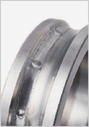
Brinelling is often caused by shock or impact loads that exceed the static load capacity of the ball nut.
Image credit: Schaeffler

Vibrations are inherent in machine tool applications, where cutting or grinding operations induce vibrations in the tool, which “feeds” those forces back into the screw. Regardless of the cause, the consequence of vibratory loads is typically false brinelling, whereas severe static overload (shock or impact load) often results in true brinelling.

Both conditions produce regularly spaced indentions in the raceway of the screw shaft and can result in premature fatigue failure of the screw. Screws that experience vibrations when not moving are at an even greater risk of false brinelling, because when the screw and nut aren’t moving, there is no lubrication layer to help protect against damage to the raceway. This is why screw manufacturers often recommend shorter, more frequent lubrication intervals for ball screws that are subjected to vibration loads.

When calculating the L10 life of a ball screw, some manufacturers recommend multiplying the applied axial load by a “load factor” ranging from around 1.2 for applications with low shock and vibration forces, to 3.5 or 4 for applications with the potential for high shock loads and vibrations.

shock vibration ball screw

L = rated life of ball screw (rev)

C = dynamic load capacity (N)

F = applied axial load (N)

fw = dynamic load factor

Similarly, when comparing the applied static load to the static load capacity of the screw, manufacturers recommend that the applied static load be multiplied by a load factor ranging from 2, for low vibration and shock loads, up to 7 for machine tool applications that can encounter significant vibration or shock loads.

shock vibration ball screw

F0max = maximum permissible static load (N)

C0 = rated static load capacity (N)

S0 = static load factor


Loads due to shocks and vibrations can occur in both the axial and radial directions, but ball screws are designed to withstand only axial loads. This is why most ball screw applications incorporate linear guides — to support any radial loads that the system experiences. When sizing linear guides to be used in conjunction with a ball screw drive, it’s important to consider the potential for these additional loads due to shock and vibration.


planetary roller screw

Planetary roller screws are capable of withstanding higher loads because the rollers provide more contact points.
Image credit: Tolomatic

For applications that experience very high shock and vibration loads, planetary roller screws can provide better performance and longer life than ball screws. This is because planetary roller screws have significantly more contact points — with rollers carrying the load — so they can withstand higher dynamic and static loads.

Feature image credit: Thomson Linear

The post How to account for shock and vibration loads in ball screw drives appeared first on Linear Motion Tips.


Industrial Ethernet basics for mechanical engineers

$
0
0

Ethernet networks are ubiquitous in our daily lives — allowing computers in office, school, and commercial environments to connect to the internet, share files, and access printers and other hardware connected to the network. And there’s a reason Ethernet is so popular — it’s a simple, flexible network protocol that facilitates high-speed data transmission. But despite its overwhelming adoption, a key function of Ethernet — the routing and delivering of data — doesn’t provide the real-time, deterministic  performance required for many industrial applications, such as motion control and automation. This is why Industrial Ethernet was developed.


Real-time: A real-time network must specify a maximum amount of time in which the system transmits data. (In contrast, a non-real-time system runs at a consistent speed, with no deadline.) Real-time systems can be hard real-time or soft real-time. A hard real-time system cannot miss any deadlines. If the response time limit is exceeded, the system will experience a failure. A soft real-time system, on the other hand, can tolerate occasional violations of the response time limit. 

Deterministic: A network is deterministic if it can guarantee that data will be transmitted in a specified, predictable amount of time — not faster or slower.


Industrial Ethernet

Industrial Ethernet networks modify standard Ethernet to provide varying levels of real-time, deterministic control.
Image credit: Analog Devices, Inc.

Industrial Ethernet isn’t just one network protocol — it’s a term that describes various Ethernet-based network protocols developed specifically for industrial applications. But one thing that Industrial Ethernet networks have in common is their use of the physical hardware and internet protocols of standard Ethernet (taking advantage of its low cost and simplicity), with adaptations to other aspects of the Ethernet framework that provide various levels of real-time, deterministic communication between controllers, actuators, sensors, and other connected industrial devices.

Here’s an overview of six common Industrial Ethernet networks that you might encounter when designing and integrating linear motion systems, along with the main differentiators of each.


CC-Link IE: The Industrial Ethernet adaptation of the CC-Link network provides high-speed, real-time data exchange with a simpler hardware structure than some other IE networks. There are several variations of the CC-Link IE network, including CC-Link IE Field, primarily for field devices, and CC-Link IE Control for handling data at the controller level, as well as versions for safety controllers and for synchronized motion control applications.

EtherNet/IP: Ethernet/IP is the only Industrial Ethernet network based entirely on the Ethernet standard. (Note that the “IP” stands for “Industrial Protocol.”) This keeps its cost low and makes it familiar and easy to use for IT personnel. The “industrial” part comes from a special application layer, known as CIP, the Common Industrial Protocol, which provides a method for organizing and representing data, managing connections, and facilitating messaging on a network. EtherNet/IP is simply CIP (the application layer) implemented over standard Ethernet


Industrial Ethernet

A network protocol stack consists of multiple layers, each of which deals with a certain aspect of data transmission and management.
Image credit: PCMag Digital Group

Industrial networks are often depicted as stacked sets of instructions — referred to as layers — that define how hardware and software on the network interact to transmit and manage data. The application layer is the “top” layer in the instruction stack — it facilitates the interaction between programs or applications and the network.


Although the basic form of EtherNet/IP doesn’t provide real-time performance or guarantee data exchange within a specific time frame, several network extensions have been developed — known as CIP Motion and CIP Sync — that allow it to achieve real-time, deterministic communication within the Ethernet standard.

DeviceNet: Just as EtherNet/IP is CIP implemented over standard Ethernet, DeviceNet is CIP implemented over a CAN network. DeviceNet is primarily used for connecting many lower-level devices, such as switches and actuators, to a controller with a single cable that carries both power and data. With DeviceNet, up to 64 nodes, or devices, can be connected over a single network at a distance of up to 500 m, with a data transmission rate of 125 kbps.

EtherCAT: EtherCAT provides deterministic, hard real-time communication, and is suitable for synchronized, multi-axis motion control “out of the box,” without requiring additional hardware to achieve synchronization between multiple axes.

ProfiNET: ProfiNET is available in several versions, but the version termed ProfiNET IRT provides hard real-time communication with cycle times as low as 250 μs, making it well-suited for motion control applications.

SERCOS III: SERCOS stands for SErial Real-time COmmunication System, and as the name implies, it delivers deterministic, hard real-time communication with cycle times as low as 32.5 μs and a high degree of flexibility in topology. It also provides a fully redundant structure so that the network continues to operate even if there’s a cable break along the network.

The post Industrial Ethernet basics for mechanical engineers appeared first on Linear Motion Tips.

Industry first: XY stage with 800 x 800 mm open center

$
0
0
Intellidrives now offers open-center XY stages with travel of 600 x 600 mm and open center dimensions of 800 x 800 mm.

XY StagesThe demand for a high accuracy, robust, open-frame stages is met with Intellidrives dual-axis, large aperture stages, which address the unique needs of scanning microscopy, wafer and printed circuit board inspection, automated assembly, and a wide range of specimen and sample scanning in many types of imaging techniques and applications.

Very precise positioning and control is easily achieved through the combination of a stable, closed-loop control system and an associated joystick option. In addition, the open-center XY stages can be combined with our Z stages to form an XYZ stage ideally suited for laser scanning microscopy.

These stages can be motorized with stepper motors or with brushless servo motors with encoders

An optional high-resolution, non-contact linear encoder is available. This non-contact encoder offers exceptional repeatability and stability over a range of operating conditions. Both digital and analog output versions are available, with resolutions in the sub-micron range.

XY StagesOpen-center XY stages
  • XY stroke: 100, 200, 300, 400, or 600 mm
  • Aperture: 188, 288, 450, 488, or 800 mm
  • Repeatability: 3 μm
  • Resolution: 1 μm
  • Stepper, servo, or smart motor
  • Linear encoder option
  • Joystick option

The post Industry first: XY stage with 800 x 800 mm open center appeared first on Linear Motion Tips.

Motion basics: How to define roll, pitch, and yaw for linear systems

$
0
0

Linear guides and systems — including Cartesian robots, gantry systems, and XY tables — are typically subjected to both linear forces due to downward, upward, and side loads and rotational forces due to overhung loads. Rotational forces — also referred to as moment forces — are typically defined as roll, pitch, and yaw, based on the axis around which the system tries to rotate.


A moment is caused by a force applied at a distance. A moment force does not cause rotation, although it is often confused with torque, which is a force that does cause a body to rotate about an axis.


To define roll, pitch, and yaw in linear systems, we first need to establish the three primary axes: X, Y, and Z.

roll pitch yawThe two axes of the horizontal plane are typically defined as X and Y, with the X axis being in the direction of motion. The Y axis is orthogonal (perpendicular) to the direction of motion and is also in the horizontal plane. The Z axis is orthogonal to both the X and Y axes, but it is located in the vertical plane. (To find the positive direction of the Z axis, use the right-hand rule: point the index finger in the direction of positive X, then curl it in the direction of positive Y, and the thumb will indicate positive Z.)


In multi-axis systems, the direction of travel of the bottom axis is typically defined as the X axis. If the next axis above it is also horizontal, that axis is defined as Y, and the vertical axis (even if it is the second axis, directly on top of X), is defined as the Z axis.


Roll, pitch, and yaw are rotational forces, or moments, about the X, Y, and Z axes. Just like pure linear forces, these moment forces need to be considered when calculating bearing life or determining the suitability of a linear system to withstand static loads.

Roll: A roll moment is a force that attempts to cause a system to rotate about its X axis, from side-to-side. A good example of roll is an airplane banking.

If a linear guide was not firmly mounted to its base, a roll moment would cause it to rotate about its X axis, like this airplane banking.


Recirculating bearings with a “back-to-back,” or “O,” raceway arrangement have higher roll moment capacities than bearings with a “front-to-front,” or “X,” arrangement, due to the larger moment arm formed by the contact lines between the balls and the raceways.

raceway geometry

The back-to-back raceway arrangement (left) provides better support for roll moments caused by loads overhung to the side of the bearing.
Image credit: Bosch Rexroth


Pitch: A pitch moment attempts to cause a system to rotate about its Y axis, from front to back. To envision pitch, think of the nose of an airplane pointing downward or upward.

roll pitch yaw

Image credit: National Air and Space Museum, Smithsonian Institution

Yaw: Yaw occurs when a force attempts to cause a system to rotate about its Z axis. To visualize yaw, imagine a model airplane suspended on a string. If the wind blows just right, the airplane’s wings and nose will remain level (no rolling or pitching), but it will rotate around the string from which it’s suspended. This is yaw.

Both pitch and yaw moments put excess loads on the balls located at the ends of a linear bearing, a condition sometimes referred to as edge loading.

roll pitch yaw

Pitch and yaw moments can cause edge loading on the bearing.
Image credit: NSK


How to counteract roll, pitch, and yaw moments

Linear guides and systems have higher capacities for pure linear forces than for moment forces, so resolving moment forces into linear forces can significantly increase bearing life and reduce deflection. For roll moments, the way to accomplish this is to use two linear guides in parallel, with one or two bearings per guide. This converts the roll moment forces into pure downward and liftoff loads on each bearing.

Similarly, using two bearings on one guide can eliminate pitch moment forces, converting them to pure downward and liftoff loads on each bearing. Using two bearings on one guide also counters yaw moment forces, but in this case, the resulting forces are side (lateral) forces on each bearing.

roll pitch yaw

Using two guides with four bearings will resolve all moment forces (roll, pitch, and yaw) into pure linear forces.
Image credit: NSK

Feature image credit: Newport

The post Motion basics: How to define roll, pitch, and yaw for linear systems appeared first on Linear Motion Tips.

Things to do this summer: Become a citizen scientist

$
0
0
finished Netflix

Image credit: El Arroyo

As cities, states, and countries begin to reopen in the wake of the COVID-19 pandemic, many of us will still face restrictions for some time regarding what businesses and facilities we can access and where we can travel. This “new normal” means that most of us will still spend more time at home, or nearby, than we’re used to, and finding ways (much less, productive ways) to fill our time will become even more difficult.

If, in the past few months of staying at home, you’ve finished Netflix, perfected your sourdough bread, and sufficiently honed your cocktail-making skills, you’re probably looking for a new activity or skill to get involved with. If this is the case, consider joining a citizen science project.


National Geographic defines citizen science as “The practice of public participation and collaboration in scientific research to increase scientific knowledge. Through citizen science, people share and contribute to data monitoring and collection programs.”

Although the term “citizen science” was coined in the 1990’s by sociologist Alan Irwin, many people point to the National Audubon Society’s Christmas Bird Count, which began in 1900, as an early example of citizen science in action. In fact, “ordinary” (i.e. non-scientist) citizens have been participating in scientific research for decades, in areas such as astronomy, species counts, and environmental tracking. These activities primarily involved observation and data collection, but today, citizen science projects can include volunteers operating their own instruments, designing hardware or software, and analyzing data.

citizen science

Image credit: Citizen Science Association

If you’re interested in becoming a citizen scientist, or just want to learn more about the projects available, here are four sites that allow you to search for projects based on criteria such as subject, location, and age range (especially helpful if you want to involve kids). Project disciplines vary by site, but they extend beyond the traditional STEM subjects you would expect in a “science” project. For example, the Zooniverse includes project categories for the arts, history, language, literature, and social science.

So regardless of your area of interest, available time, or whether you’re more comfortable at your computer analyzing data or out in the field gathering data, there’s a citizen project for just about everyone.


SciStarterSciStarter Logo

SciStarter is “an online community dedicated to improving the citizen science experience for project managers and participants.” SciStarter is the result of a graduate project at University of Pennsylvania and is now managed in part by Arizona State University.

Example Project: Speak to AI – An online, multiplayer word game to help advance artificial intelligence.


ZooniverseZooniverse Logo

The Zooniverse is a “platform for people-powered research” and is a collaboration between the University of Oxford, Chicago’s Adler Planetarium, and the University of Minnesota – Twin Cities, together with hundreds of researchers and millions of participants (citizen scientists) from around the world.

Example Project: Snapshot Serengeti – Classify animals caught on camera in Serengeti National Park to help conservationists learn what management strategies work best to protect some of Africa’s most elusive wildlife.


NASA logoNASA Citizen Science Projects

The NASA Citizen Science website lets you participate in real NASA science projects. Focus areas include the universe, the solar system, the sun, and the earth.

Example Project: Backyard Worlds: Planet 9 – Search the realm beyond Neptune for new brown dwarfs and planets.


citizen sciencecitizenscience.gov

This is an official government website “designed to accelerate the use of crowdsourcing and citizen science across the U.S. government.”

Example Project: The Milky Way Project – Analyze infrared images of the Milky Way Galaxy to help scientists understand how stars form and discover massive stars.


The post Things to do this summer: Become a citizen scientist appeared first on Linear Motion Tips.

Linear guides with more rollers feature high load capacities

$
0
0

NB Corporation’s EXRAIL linear guide has more rollers in less space than other linear bearings, which increases load capacity and disperses the load more evenly. It has longer rollers for greater contact surface and less contact pressure.

In comparison to presently available linear guides, the EXRAIL slide guide provides smoother movement. It uses multiple small diameter needle rollers that reduce dynamic frictional resistance and range of fluctuation of dynamic frictional resistance.

linear guides

Another EXRAIL feature is that its static load capacity is higher. Localized deformation occurs when a slide guide receives load in pitch, yaw, or roll directions. High static load capacity means that there’s a fairly large amount of load that the block can sustain before it deforms. In fact, for the new design, independent testing data indicated that it exhibited higher performance than presently available products.

The EXRAIL has a 1.5 to 2 times higher static load rating as well as allowable static moment in the rolling, pitching, and yawing directions in comparison to other products on the market. And the EXRAIL retainer prevents skews and friction ensuring smooth circulation.

Lubrication intervals are extended by EXRAIL’s maintenance features. Its rollers are in contact with lubricated resin material during circulation and its 4 oil holes make relubrication easy. It has side, under and inner seals that improve dust prevention.

For more information, visit www.nbcorporation.com.


The post Linear guides with more rollers feature high load capacities appeared first on Linear Motion Tips.

New 20-mm linear stepper motors from Nippon Pulse

$
0
0

Nippon Pulse has introduced its smallest linear stepper motor yet, the PFL20 Linearstep. The PFL20 is a highly efficient, high thrust tin-can linear actuator with a 20-mm diameter and a bipolar winding.

The PFL20 is RoHS-compliant, has a 30/60 mm effective stroke, and can reach 6 N of force at 200 pps. With 24 steps per revolution, the lead screw has a 1.2-mm thread pitch. The PFL20 also reaches 5-V rated voltage, has a resistance of 33 Ω/phase and inductance of 12 mH/phase.

linear motor

The simple structure of Linearstep motors (just a threaded rotor hub and lead screw) helps to save space and reduce costs, due to fewer components needed compared to systems that convert rotary motion to linear. Linearstep motors are also easy to control, and can be ordered with unipolar or bipolar windings and a variety of usable voltages. In addition to the 20-mm motor size, this motor is also available in 25-mm (captive or non-captive option) and 35-mm diameter sizes.

Nippon Pulse’s tin-can linear actuators, including the Linearstep, are also available for customization; contact an applications engineer to learn more about our customization capabilities.

More Information on the PFL20 linear stepper motor from Nippon Pulse can be viewed here: https://www.electromate.com/pub/media/assets/catalog-library/pdfs/nippon-pulse/nippon-pulse-pfl20-specsheet.pdf.

www.nipponpulse.com


The post New 20-mm linear stepper motors from Nippon Pulse appeared first on Linear Motion Tips.

Linear motion in medical applications: Piezo motors for liquid handling robots

$
0
0

Piezo motors and actuators are used in a variety of medical applications, including liquid handling robots for laboratory testing and diagnostics, drug discovery, and biotechnology. 


Liquid handling functions in the medical industry have traditionally been done manually by laboratory personnel. But consistency and accuracy are difficult to ensure with manual methods, since variations between technicians (and even between individual processes by the same technician) are inevitable. And manual pipetting for multiple hours each day can cause repetitive strain injuries and introduces the risk of accidents, such as spills or misapplications. For these reasons, automated liquid handling robots have become widely accepted, not only in large pharmaceutical labs and testing facilities, but in smaller-scale laboratories and medical offices as well.

manual pipetting

Manual pipetting introduces the risk of errors, accidents, and injury.
Image credit: Opentrons

Automated liquid handlers ensure consistency, accuracy, and safety, without the variations in process or timing that plague manual dispensing methods. And as typical dispensing volumes move from microliters (1.0 x 10⁻³ mL), to nanoliters (1.0 x 10⁻⁶ mL), all the way down to picoliter (1.0 x 10⁻⁹ mL) amounts, automated liquid handling robots can provide the speed and precision necessary to achieve high throughput while handling these minute volumes of liquids.


Liquid handling terminology

In the medical industry, the device that transfers the fluid is typically a pipette, although needles and pins can also be used to transfer fluids.

The process of taking in the liquid to be transferred is referred to as aspiration, and the processes of expelling the liquid into the target container can be referred to as either dispensing or pipetting.

Pipetting typically refers to a method of dispensing in which there is contact between the pipette tip and the receiving container or fluid, with surface tension holding the liquid in place once the pipette is retracted. Pipetting also typically implies that all the liquid that is aspirated is expelled in one dispensing cycle.

When the term “dispensing” is used, it typically implies that the process is non-contact — that is, there is no contact between the pipette tip and the receiving container or liquid. Dispensing can also refer to a process in which a certain volume of liquid is aspirated, and the liquid is expelled in smaller amounts to multiple targets over multiple dispensing cycles. The process of aspirating enough total volume to expel more than once from the same pipette is often referred to as aliquoting.


liquid handling robots

Well-to-well spacing on a 384-well plate is only 4.5 mm. On a 1536-well plate, spacing between wells goes down to just 2.25 mm.
Image credit: PerkinElmer

Automated pipetting

Pipetting, or contact dispensing, is the most common method for dispensing microliter and nanoliter volumes of liquids. In automated systems, the liquid is typically dispensed into a microplate — a small plate with evenly spaced “wells” arranged in rows and columns. The most common microplate formats are 96-well (8 rows x 12 columns), 384-well (16 rows x 24 columns) and 1536-well (32 rows x 48 columns). Regardless of the number of wells, the dimensions of the microplate remain the same, at approximately 128 mm x 85 mm.

The most common format is the 384-well plate, but more applications are moving to the 1536-well format to increase throughput and reduce the volume of samples and reagents required for each test. To enable this, dispensing heads often include multiple pipettes, referred to as channels. Multichannel dispensers typically include 6, 8, or 12 channels in one dispensing head. In these applications, a Cartesian robot or gantry system positions the dispensing head in the X and Y directions over the microplate and then moves the individual pipette tips vertically into position above the target wells.

The X-Y motion of the dispensing head is mostly unaffected by the microplate format, since the plate dimensions are the same regardless of the number of wells. But as the number of wells on the microplate increases (from 96 to 384 to 1536), the distance between wells decreases, and the system that controls the Z-axis motion of the individual channels must be even more precise. The dispensing head must also be more and more compact to allow the individual pipette tips to align with the wells on the plate. This is important not only for accurate dispensing, but also to avoid hard contact between the pipette tip and the well. Piezo motors are the perfect solution to meet the requirements of both compact dimensions and high-precision positioning.

liquid handling robots

Multichannel dispensing heads increase throughput, which is especially important for diagnostic testing and drug discovery.
Image credit: Tecan

Even small-diameter ball and lead screws can be too bulky once motors and other components are assembled. And at small diameters and leads, high speeds become difficult to achieve, not to mention the effects of friction and backlash that degrade positioning accuracy and repeatability.

For liquid handling applications, linear ultrasonic piezo motors can provide stroke lengths up to 100 mm, with resolution of less than 10 microns, to move pipette tips into the optimal position for accurate contact dispensing. Because piezo motors are direct drive, they don’t suffer from mechanical losses, and their high dynamics allow them to produce the forces required for quickly extending and retracting the pipettes for high-throughput dispensing.

The post Linear motion in medical applications: Piezo motors for liquid handling robots appeared first on Linear Motion Tips.


Linear motion in medical applications: Piezo actuators for non-contact dispensing

$
0
0

In a recent article, we looked at how piezo motors are used in liquid handling robots for contact-based dispensing (also referred to as pipetting) of microliter and nanoliter volumes. But when the required dispense volumes fall in the single-digit nanoliter or picoliter range, the process often requires a non-contact dispensing method to ensure accuracy and reliability of the dispense volume.


Non-contact dispensing is sometimes referred to as “jetting,” since it involves ejecting fluid from an orifice. This is in contrast to contact-based dispensing methods, which rely on surface tension between the fluid and the receiving container to hold the fluid at the target location when the pipette or dispensing head is removed.


There are several ways to achieve non-contact dispensing, but two common methods in the medical liquid handling industry use piezo actuators to create very small drops of fluid by deforming a small tube or actuating a valve.

In the first method, a piston — driven by a piezo stack actuator — partially deforms a thin-walled polymer tube or silicon dispensing element, which squeezes off and forces out a droplet of liquid. This method enables highly repeatable dispensing of drop sizes ranging from single nanoliters down to picoliters.

non-contact dispensing

The PipeJet non-contact dispenser is driven by a piezo stack actuator and can dispense volumes as small as 2 nL.
Image credit: Biofluidix

A similar method uses a capillary tube (typically made of glass for medical applications, although quartz and steel are other possible materials) with a piezo actuator formed as a collar around the capillary. When voltage is applied, the piezo collar contracts, causing pressure on the glass, which forces liquid from the tip of the capillary.

Piezo-driven dispensing valves use a piezo stack or piezo flexure mechanism to actuate a rod connected to a sealing ball. The ball is seated on the nozzle of the valve and may be held in place by a spring. When voltage is applied to the piezo actuator, it actuates the rod and raises the ball from the valve seat by a very small amount — typically in the range of 100 to 200 microns.

In some piezo valve designs, the fluid is pressurized and flows when the ball is raised. When voltage is removed, the ball drops and stops the flow of pressurized fluid, In other designs, the rapid falling of the ball ejects fluid from the nozzle. In either case, the amount of dispensed fluid depends on both the time and the distance the ball is raised.

peizo-driven valve for non-contact dispensing

Piezo flexure actuators can achieve position resolution in the nanometer-range for dispensing very small volumes. And their fast response and high operating frequency enables quick dispensing for high-throughput applications.
Image credit: Physik Instrumente


In addition to extremely small dispensing volumes, another important benefit of non-contact dispensing is its speed. Contact-based dispensing methods require Z-axis motion to move the pipette tip into position to make contact with the substrate, which adds time to the dispensing cycle.

Non-contact dispensers don’t require movement in the Z-axis, so a full step is eliminated from the dispensing cycle. This reduced motion time, combined with the rapid expansion and contraction of the piezo actuator, makes non-contact methods much faster than their contact-based counterparts. Case in point — some piezo jetting techniques can dispense liquids at 1000 to 1500 Hz (drops per second).


Image credit: Biofluidix

Although contact-based dispensing is still the dominant method in the medical industry, the shear cost and overall value of reagents and samples is driving the development of testing processes that can use smaller and smaller amounts of these fluids, making non-contact dispensing methods a necessity in some drug discovery and diagnostic processes.

One such process is the creation of ELISA assays for antibody tests, including the antibody test for COVID-19. Other uses include bioengineering, where individual cells are dispensed onto a scaffold to create artificial bones or cartilage, and dispensing reagents and samples onto test strips for monitoring blood glucose or insulin.

The post Linear motion in medical applications: Piezo actuators for non-contact dispensing appeared first on Linear Motion Tips.

How to specify pulleys for synchronous belt drives

$
0
0

When designing a belt drive system, the first step is to choose the most suitable belt for the application. But the pulleys also play an important role in the performance of the belt — especially in synchronous belt drive systems, where proper meshing of the belt teeth with the pulley grooves can affect everything from the amount of torque that can be transmitted to the belt’s rate of wear and potential failure modes.


Synchronous belt pulleys are typically designated by the number of grooves (analogous to the number of teeth on the belt), groove pitch (analogous to the belt tooth pitch), and pulley width.

The required tooth pitch (and, therefore, groove pitch) is determined during belt selection, based on the design torque and speed. Torque and speed are also the primary factors in determining belt width, and, therefore pulley width. (Recommended pulley width is typically slightly larger than the belt width and takes into account the space required for pulley flanges.) The number of pulley grooves is determined by the required speed ratio.

synchronous belt profiles

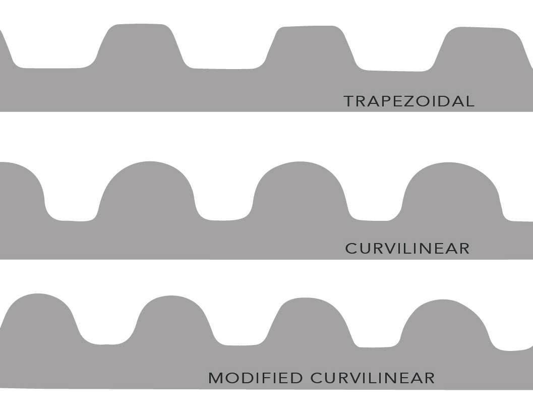
For pulleys used with synchronous (toothed) belts, it’s important that the pulley grooves match the belt tooth profile — trapezoidal, curvilinear, or modified curvilinear.

Dimensional information also includes the type and size of hub for attaching the pulley to the drive shaft. Common options for pulley mounting include taper lock bushings, split taper bushings, QD (quick disconnect) bushings, or plain bores with or without keyways.


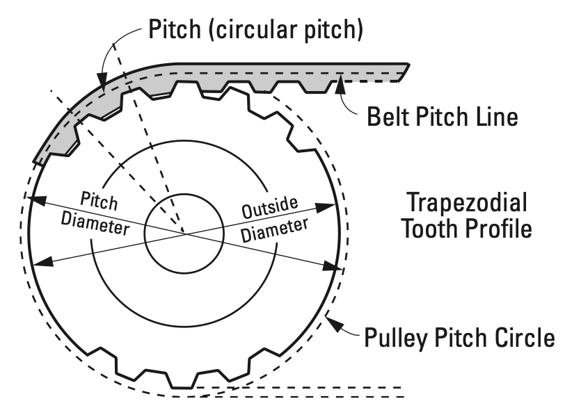
Although pulley diameter isn’t explicitly specified during selection, it can be determined by the number of pulley grooves and their pitch, which are used to calculate the pitch diameter of the pulley. The pitch diameter is slightly larger than the outer diameter of the pulley and corresponds to the pitch line of the belt, which is the line formed by the belt’s tensile cord.

pulleys for synchronous belt

pd = pulley pitch diameter (mm, in)

P = pulley groove pitch (also belt tooth pitch) (mm, in)

N = number of pulley grooves

belt and pulley dimensions

The pulley outer diameter (O.D.) is slightly smaller than its pitch diameter.
Image credit: Pfeifer Industries

Once the pitch diameter is calculated, the pulley’s outer diameter can be determined by finding the distance from the belt pitch line to the bottom of the tooth profile (a value specified by the belt manufacturer), and subtracting twice that distance from the pulley pitch diameter.

pulleys for synchronous belt

O.D. = pulley outer diameter (mm, in)

U = distance from belt pitch line to bottom of tooth profile (mm, in)

pulleys for synchronous belt


Some manufacturers offer pulleys in the form of bar stock, to be cut and machined by the user. While this can be an economical solution for prototyping small quantities, the accuracy of the pulley is critical to ensure proper belt tracking, speed ratio, and efficiency.

Acceptable pulley tolerances are specified by trade associations (such as the Mechanical Power Transmission Association, MPTA) and by the International Standards Organization (ISO). In some cases, major belt manufacturers also specify tolerances for specific tooth profiles.

Key manufacturing tolerances for synchronous belt pulleys include:

  • pulley outer diameter
  • eccentricity between pulley bore and pulley outer diameter
  • parallelism between pulley bore and vertical faces of the pulley
  • pitch accuracy of grooves
  • parallelism between grooves and bore.

It’s important to note that pulleys may also need to undergo static or dynamic balancing after manufacturing.


Synchronous belt pulleys can be made from a wide range of materials, including aluminum, steel, cast iron, and various plastics. The material of the pulley determines its weight and inertia, and so affects the dynamic performance of the belt drive system. Material selection also influences the amount of noise generated by the system, with polycarbonate (thermoplastic polymer) pulleys generating more noise during operation than metal pulleys.

flanged pulleys

In most synchronous belt drive systems, at least one pulley should be flanged.
Image credit: Brecoflex Co., LLC

To prevent the belt from riding off the pulley, and to resist the lateral forces caused by the belt’s side-to-side motion, synchronous belt drives typically require flanged pulleys. In general, manufacturers recommend that synchronous belt systems include at least one pulley with flanges, although there are exceptions to these guidelines, as noted in this article on pulley flanges.

The post How to specify pulleys for synchronous belt drives appeared first on Linear Motion Tips.

igus develops new online shop for energy chains

$
0
0

igus has developed a new online shop for energy chains where designers can filter products by category, application, and specifications. The new shop also includes pricing, and allows designers, engineers, and materials specialists to have all of the parts listed in one user-friendly website. The shop can be accessed here: https://www.igus.com/e-chains/cable-carriers

The new shop allows users to enter the dimensions and filter e-chains by inner height, inner width, and bend radius. Users can also filter searches by unsupported length, fill weight, speed, and acceleration. With a few simple strokes, product designers can choose and purchase the energy chain that best suits their application requirements.

igus

Energy chains from igus can be used in small and large applications. The company’s E2, E-Z and triflex chains are frequently used in office management, automotive industry, and in low-cost automation tasks such as multi-axis robots, gantries, and delta robots.

Its larger energy chains, such as E4, E6, P4, twisterchains and guide troughs, are used in the oil and gas industry, bulk material handling and mining industries. They are also frequently found on port and terminal cranes as well as indoor and electric overhead traveling cranes.

More information is also available by ordering the e-chain catalog.


The post igus develops new online shop for energy chains appeared first on Linear Motion Tips.

Three important design considerations for Cartesian robots

$
0
0

If your application calls for a Cartesian robot, you have a wide variety of options, depending on the level of  integration you want to undertake. And although pre-engineered Cartesian robots are becoming more widely adopted as manufacturers expand their product ranges to fit a broader scope of performance criteria, some applications still necessitate building your own Cartesian system — for example, to meet special environmental conditions or to fulfill a highly specialized set of performance requirements.

Cartesian robots

Cartesian robots are available in almost any combination of X, Y, and Z axes you can image.
Here are a few examples of 3-axis Cartesian systems from IAI.

But “build your own” doesn’t necessarily mean “build from scratch.” Case in point: the key components of a Cartesian robot — the linear actuators — are available in numerous configurations, so it’s rarely necessary to build the actuators from scratch. And many linear actuator manufacturers offer connecting kits and mounting brackets that make assembling your own Cartesian system from catalog-spec actuators a relatively simple exercise.

However, determining the basic layout and choosing the appropriate linear actuators is only the first step. To avoid ending up with a Cartesian system that doesn’t perform to the application requirements or doesn’t fit in the expected footprint, keep the following considerations in mind — especially during the design stage.


System configuration

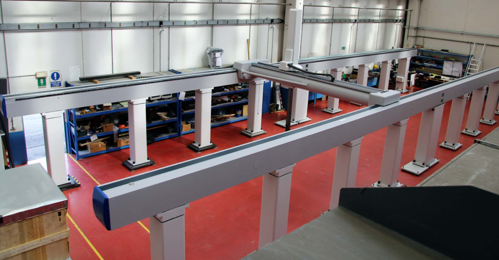
One of the first things to specify when designing a Cartesian robot is the configuration of the axes, not only to achieve the necessary movements, but also to ensure the system has sufficient rigidity, which can affect load-carrying capacity, travel accuracy, and positioning accuracy. In fact, some applications that require movement in the Cartesian coordinates are better served by a gantry robot than by a Cartesian system, especially if the Y axis requires a long stroke or if the Cartesian arrangement would put a large moment load on one of the axes. In these cases, the dual-X or dual-Y axes of a gantry system may be necessary to prevent excessive deflection or vibration.

If a Cartesian system is the best solution, the next design option is typically the drive unit for the actuators — with the most common choices being a belt, screw, or pneumatic-driven system. And regardless of the drive system, linear actuators are typically offered with either a single linear guide or dual linear guides.

The vast majority of Cartesian robots use the dual-guide configuration, since it offers better support for overhung (moment) loads — but axes with dual linear guides will have a wider footprint than axes with single linear guides. On the other hand, dual-guide systems are often shorter (in the vertical direction), which can prevent interference with other parts of the machine. The point is, the type of axes you choose affects not only the performance of the Cartesian system, it also affects the overall footprint.

gantry robot

Long strokes – especially on the Y axis – can result in significant overhung loads on Cartesian robots. In these cases, a gantry system may be a better choice.
Image credit: Coord3


When thinking about the system’s footprint, don’t forget about end effectors or end-of-arm (EOA) tooling that will need to be incorporated. It’s important to consider this early in the design stage to ensure there are no interferences between tools such as grippers or dispensing heads and the other components of the Cartesian system or the machine itself.

Cartesian robots

The layout of a Cartesian robot – including end-of-arm tooling – needs to be carefully planned to ensure there’s no interference between axes or with other parts of the machine.
Image credit: Fisnar


Cable management

Another important aspect of Cartesian robot design that’s often overlooked in the early phases (or simply deferred to later phases of the design) is the cable management. Each axis requires multiple cables for power, air (for pneumatic axes), encoder feedback (for servo-driven Cartesians), sensors, and other electrical components. And when systems and components are integrated into the Industrial Internet of Things (IIoT), the methods and tools for connecting them becomes even more critical. All of these cables, wires, and connectors must be carefully routed and managed to ensure they don’t experience premature fatigue due to excessive flexing or damage due to interference with other parts of the system.

networking

Modern industrial networks enable highly complex, coordinated motion, safety integration, and remote monitoring of machines and systems. But this connectivity can also make physical cabling and connections more complex. Integrated motor-drive combinations and smart networking and communication choices can reduce this complexity.
Image credit: Texas Instruments

Cartesian (as well as SCARA and 6-axis) robots make this connectivity even more challenging, since the axes can move both independently and in synchronization with each other. But one thing that can help mitigate the complexity of cable management is to use components that reduce the number of cables required — for example, motors that integrate power and feedback into a single cable, or integrated motor-drive combinations.

The type of control and the network protocol can also influence the type and quantity of cables required and the complexity of cable management. And don’t forget that the cable management system — cable carriers, trays, or housings — will affect the dimensions of the overall system, so it’s important to check for interference between the cable management system and the other parts of the robot and the machine.


Controls

Cartesian robots

The most compact Cartesian robots use integrated motor-drive combinations to reduce space and cabling.
Image credit: Precise Automation

Cartesian robots are the go-to solution for point-to-point moves, but they can also produce complex interpolated moves and contoured motion. The type of motion required will help determine what control system, networking protocol, HMI, and other motion components are best suited for the system. And although these components are, for the most part, housed separately from the axes of the Cartesian robot, they will influence what motors, cables, and other on-axis electrical components are required. And these on-axis components will, in turn, play a role in the first two design considerations: configuration and cable management.

So the design process comes “full-circle,” reiterating the importance of designing a Cartesian robot as an integrated electromechanical unit, rather than a series of mechanical components that are simply connected to electrical hardware and software.

The post Three important design considerations for Cartesian robots appeared first on Linear Motion Tips.

What are boxway slides and where are they used?

$
0
0

Recirculating linear guides get significant media attention, thanks to their versatility and wide range of uses. But linear guides based on sliding contact — namely boxway and dovetail slides — are often the bearings of choice for applications that call for high load capacity, extreme stiffness, and excellent vibration damping characteristics.

boxway

Boxway slides (left) are a type of plain linear guide, with no recirculating balls or rollers like profiled rail guides (right).


Boxway slides are a type of plain linear bearing, with a somewhat “T-shaped” base and a mating saddle, or carriage, that fits around the profile of the “T.” This geometry gives boxway designs a large area of contact between the base (stationary part) and the saddle (moving part), which results in extremely high load capacities. In fact, boxway slides typically have the highest load capacities and highest stiffness of any linear guide system — rolling or sliding. The downside of this sliding contact is increased friction, which lowers the permissible speed, although speed isn’t typically an issue for the heavy-duty machining applications where boxways are most often used.

boxway

Image credit: Bosch Rexroth

The base and saddle of a boxway slide can both be made from cast iron, or the base can be made from cast iron and the saddle from steel. The ways — the surfaces on the underside of the saddle that actually ride on the base — are typically coated with a friction-reducing material such as Turcite or Rulon, both of which are reinforced PTFE-based materials. These non-metallic coatings offer superior protection against the effects of stick-slip and corrosion and, together with the shear mass of the boxway assembly, contribute to the slide’s vibration-damping capabilities.

Because of their large contact area, boxways require very precise manufacturing tolerances. The saddle and base are precision-ground (top and bottom) to ensure parallelism and flatness of travel. And most boxway slides have hand-scraped ways that improve accuracy, reduce friction, and create pockets for lubrication, which is typically provided via a pressurized oil-delivery system.

One or more adjustable plates, referred to as “gibs” or “gib plates” are used in boxway slides to remove clearance between the base and the saddle and create preload, which is typically required for machine tool applications to improve rigidity and accuracy.


An example of a hand-scraping. The blue spots indicate contact points between the bearing surfaces.
Image credit: Devitt Machinery Company

Scraping is the process of creating high and low spots on mating bearing surfaces. The high spots created by scraping ensure even distribution of the load and prevent one surface from “rocking” on the other. The combination of high and low spots creates pockets that hold oil, ensuring proper lubrication between the surfaces — especially during startup.

Scraping is almost exclusively done by hand (known as “hand-scraping“) by highly skilled technicians who analyze the interferences between surfaces and determine where scraping is needed. In boxway manufacturing, the goal of hand scraping is typically to create 10 to 15 contact points per square inch.


In addition to higher load capacity and better rigidity, boxway slides can also provide significant damping for machine vibrations — something that recirculating linear guides, with only point or line contact, cannot provide. Vibration damping not only improves the surface finish and accuracy of the machining process, it can also increase tool life by reducing small but destructive vibrations in the tool.

While recirculating profiled rail bearings and dovetail slides are used in many machine tool applications, boxways are the primary choice for machine tools designed for high-horsepower, “hard” cuts and for materials that are especially difficult to machine, such as aerospace alloys.

Feature image credit: Gilman Precision

The post What are boxway slides and where are they used? appeared first on Linear Motion Tips.

Electromechanical linear actuators feature embedded CAN bus support, PLC capability

$
0
0

Thomson Industries, Inc. has unveiled their new Electrak MD, a more compact electromechanical actuator that retains all of the intelligence built into its larger counterparts. Mobile off-highway, material handling and factory automation applications can benefit from the compact actuator with up to two kilonewtons (kN) of force, advanced onboard electronics and J1939 CAN Bus support.

“Traditionally, motion control users looking for a higher load handling system are using hydraulic actuators,” said Chad Carlberg, Product Line Manager for Industrial Actuators at Thomson. “However, these actuators are costly to maintain and use a lot of space. With our new compact Electrak MD, designers can now achieve high precision and greater flexibility while reducing costs.”

linear actuator

Onboard Electronics
The new Electrak MD also comes with onboard intelligence, which enhances the overall performance and eliminates space consumption by keeping any external equipment like encoders and switches within the actuator housing. As with its predecessor, the Electrak HD, this functionality provides a simpler method of control and communication, which minimizes operating costs and simplifies setup and installation.

In addition to the above benefits, the Electrak MD also features extensive automation and maintenance enablers such as feedback on position, J1939 CAN bus communication, low-current switching (PLC compatibility), and end-of-stroke indication output.

linear actuator

High Power Density
Many design engineers are often faced with the challenge of meeting size constraints while maintaining high force requirements. For example, with applications on a harvesting combine, past designs were cavernous enough to allow a large amount of space for hydraulic solutions to actuate the equipment with high force. Now, equipment manufacturers are tasked with reducing the overall footprint and adding functionality, resulting in an increased demand for more compact components such as the power-dense and intelligent Electrak MD.

 Electrak MD actuators are available immediately. For more information, visit: https://www.thomsonlinear.com/en/products/linear-actuators/electrak-md

The post Electromechanical linear actuators feature embedded CAN bus support, PLC capability appeared first on Linear Motion Tips.

AutomationDirect adds inductive linear position transducers

$
0
0

Linear Variable Inductance Transducers (LVITs) from Alliance Sensors Group convert the linear displacement of an object into a proportional electrical signal output of 0 to 10 V or 4 to 20 mA (depending on model). LVITs are contactless devices designed for dimension or position measuring applications where the sensing element cannot be attached to the object being measured. LVITs exhibit outstanding repeatability and are used in applications requiring higher accuracy.

The Alliance LVIT proprietary SenSet process provides the ability to match the end points of the sensor’s analog output with the ends of the range of motion of a workpiece (such as a hydraulic cylinder ram) in which the sensor is installed. The SenSet feature permits users to optimize the position measuring system resolution over the full range of motion.

linear position sensors

Configuration styles include spring loaded with ball tip, 19 mm (0.75 in.) cylinder with rod eye mounting, and 27 mm (1.05 in.) cylinder with rod eyes. Stroke lengths vary from 6.35 mm (0.25 in.) to 457.2 mm (18 in.).

Priced from $299.00, AutomationDirect’s Alliance Sensors Group inductive linear position transducers are CE, RoHS approved and have a 1-year warranty.

For more information, visit www.automationdirect.com/inductive-linear-transducers.


The post AutomationDirect adds inductive linear position transducers appeared first on Linear Motion Tips.


LinX M-Series electric actuators from ANCA Motion offer direct replacement of pneumatic cylinders

$
0
0

Pneumatics (and compressed air) are indispensable in many industrial applications. They’re cost-effective and easy-to-understand technologies that are rugged enough to run in even very challenging environments. The problem is that some facilities can spend up to 30% of their electricity bill on generating compressed air. Because pneumatic actuators for linear motion (which have been an option to design engineers since WWII) run on compressed air, they’re one type of component that can degrade the overall efficiency of an automated operation. well-understood, cheap, and suited to harsh environments.

Depending on the expansiveness of a factory, arrays of pneumatics can require numerous compressors … or a complicated reticulation system. After all, a reliable level of pressure must be maintained — or the pneumatic actuators will work poorly or not at all.

But air leaks do happen … and they’re expensive. According to one compressor technology company, a leak in one component costing 15¢ per kW-hr can add well over $2,000 to the yearly power bill.  With a single point of failure (such as air leakage at a degraded seal, for example) the air pressure of the whole plant will drop … and operations will be less than optimal.

Another problem is noise. “When working in or visiting a factory, you’ll usually hear a lot of noise,” explains ANCA Motion product manager Heng Luo. “That’s one big advantage servo-controlled linear motors have over pneumatics” that they’re much quieter adds Luo.

Linear actuators such as those base don rotary motors (with rotary-to-linear screw components) as well as true tubular linear motors are newer than pneumatic as well as hydraulic linear actuation. Though somewhat more complicated to integrate and control, these are electric-motor-based linear actuators are preferred for certain applications. Instead of a piston in a cylinder driven by compressed air or an incompressible fluid, tubular linear motors use magnetic flux to create motion. They have a higher upfront costs than pneumatics, but offer vast benefits in aspects including accuracy, cheaper operating costs, and flexibility.

In addition, linear actuators based on traditional pneumatics can move quickly and forcefully from one point to another (and hydraulics quicker and more forcefully still for the same size) but with little positional control along the stroke.

One option for motor-based actuation is ANCA Motion’s LinX M-Series offers 10-μm resolution as well as velocities to 10 m/sec as well as:

• Maximum acceleration of more than 30 g
• An integrated position sensor with precise positional control
• Continuous force of 90 to 160 N
• Peak force to 1,200 N

The estimated payback period (return on upfront investment) for the M-Series electric linear actuators is also much shorter than that for pneumatic cylinders of comparable form factor and mounting design— typically around 18 months.

Another advantage of -Series electric linear actuators is ease of reprogramming.  In one recent application, an end user’s forming machine substituted LinX motors for pneumatics to move a cutting bed. Changes for different workpiece lengths could take six to eight hours for the painstaking recalibration of air pressure. Such adjustments now are a quick change in servo drive parameters — a matter of seconds. The improved positional control has boosted throughput by 50% with the massively improved precision for higher throughput.

ANCA Motion’s linear motors were originally developed for sister company ANCA CNC Machines’ FX Linear and MX Linear tool and cutter grinder machines. ANCA is a leader in CNC tool grinding technology, with a series of world firsts since beginning in 1974. In fact, the LinX M-Series Tubular Linear Motor has a failure rate of less than 0.03% … and robust support is offered through an international network of 125 engineers in strategic locations. For more information,  visit this deep link on motion.anca.com.

The post LinX M-Series electric actuators from ANCA Motion offer direct replacement of pneumatic cylinders appeared first on Linear Motion Tips.

ElectroCraft expands AxialPower family of linear actuators with the APES 17

$
0
0

ElectroCraft has recently expanded the AxialPower enhanced series of linear actuators to include a new high-performance 42mm (NEMA 17) frame size. This new linear actuator is highly configurable and:

• Is available with a variety of imperial or metric leadscrew options
• Achieves resolutions of 0.006 mm to 0.050 mm per step
• Delivers output force of up to 1,001 N (225 lb)
• Offers 40% more force than competitive size-17 designs

ElectroCraft hybrid stepper-based linear actuators provide original equipment manufacturers the precision, performance, and reliability required for a wide variety of motion-control positioning applications. From medical and laboratory equipment to industrial machinery, ElectroCraft offers configurable to completely customizable solutions in three unique product designs:

• Linear actuator (non-captive)
• Leadscrew motor (external linear)
• Guided linear actuator (captive)

Fractional-horsepower motor and motion solutions provider ElectroCraft Inc. has expanded its linear actuator lineup for the AxialPower family with the APES17.

“ElectroCraft’s unique motor, shaft and insert designs offer industry-leading linear force per frame size while providing superior precision, speed and efficiency,” notes Scott Rohlfs of ElectroCraft.

“These new actuators are suitable for a wide variety of medical and laboratory applications including precision metering pumps, mass spectrometers, gas and liquid chromatography systems, medical imaging systems, sample handling and dispensing systems, allowing equipment manufacturers to reduce product footprints while significantly increasing performance.”

ElectroCraft’s AxialPower family of linear actuator products come in the most used frame sizes — including 28 mm (NEMA 11), 42 mm (NEMA 17), 56 mm (NEMA 23), and 86 mm (NEMA 34). For more information, visit www.electrocraft.com.


ElectroCraft Inc. custom manufacturing services cover ac motors, PMDC motors, brushless dc motors, stepper motors, servo motors, gearboxes, gearmotors, linear actuators, drives, servo drives, and integrated motor drives. The manufacturer’s products are found in thousands of different applications within industrial, commercial, and consumer product markets. For OEM Design engineers who are unsatisfied with having to design around inflexible off-the-shelf products, ElectroCraft technical knowledge and customizable product families provide for a design experience which results in motor and motion systems that provide superior reliability and performance at the lowest possible cost.

The post ElectroCraft expands AxialPower family of linear actuators with the APES 17 appeared first on Linear Motion Tips.

What are planar motors and where are they used?

$
0
0

Ironless linear motor
Image credit: Rockwell Automation

Linear motors are often described as rotary motors cut open and rolled out flat, so they produce motion in a straight line along one axis. Their construction is relatively simple, with a primary part (also referred to as a forcer) that contains windings, and a secondary part that contains magnets. The primary part is typically the moving part, and the secondary part is typically stationary. In iron core linear motors, the secondary part is laid out like a track, and in ironless designs, the secondary part is often constructed with two magnet tracks facing each other and the primary part riding between the two magnet tracks. Support for the moved load is provided by recirculating linear guides or air bearings.

Planar motors are built on the same basic principle as traditional linear motors, but a key difference between traditional linear motors and planar motors is that the planar design allows the moving part — often referred to as a tile — to travel in two horizontal directions, X and Y (hence, the term “planar” motors). And instead of moving only in straight lines, the tiles can move in free-form patterns that include diagonals and curves. In some planar motor designs, the tiles can also tilt and rotate and even make small movements in the vertical (Z) direction.

planar motors

Planar motors can travel in both the X and Y directions and along free-form paths.
Image credit: Planar Motor Incorporated

Two designs of planar motors exist. In the first design, the tiles (also referred to as movers or floaters) contain iron cores embedded in epoxy, with windings and permanent magnets, while the stationary stator contains a toothed structure with sets of teeth arranged at right angles to each other in the X-Y plane. The tiles also include nozzles for an air bearing system, which provides support for the tiles and the moved load. Although this design is relatively simple to implement, each tile requires motor and feedback cables, as well as pneumatic lines for the air bearing system, so cable management is necessary for each tile.

planar motors

In one planar motor design, the windings and magnets, as well as air bearing nozzles, are located in the moving tiles.
Image credit: Schaeffler

Another planar motor design uses a 2D coil matrix in the stator to produce 3D magnetic fields, which lift the tiles 1 to 5 millimeters above the stator surface. Because the tiles can “levitate,” this design is sometimes referred to as a “maglev” motor. The benefit of this planar motor design is that the tiles are completely passive — all the required cabling is connected to the stator, leaving the tiles free of the constraints of cables and cable management.

planar motors

Some planar motor designs allow the tiles to move with six degrees of freedom, so loads can be lifted, tilted, and rotated, as well as moved in arbitrary paths over the stationary stators.
Image credit: Beckhoff Automation


Stators can be arranged in virtually any configuration, to route around other machines and equipment or to provide buffer zones for conveying applications.
Image credit: Planar Motor Incorporated

In both planar motor designs, there are no moving parts, so reliability is excellent, and the systems can be designed for extremely demanding environments, such as cleanrooms, vacuum environments, and hygienic applications. And planar motors can use multiple stators connected in virtually any pattern, from squares and rectangles to complex paths that traverse around other equipment or obstacles — much like the configurability of a conveyor system. Some designs can even be used in overhead (upside-down) and vertical (wall-mounted) orientations.

With virtually unlimited travel configurations and tiles that can move with six degrees of freedom, planar motors are being used as conveyors for light payloads and in assembly, inspection, and semiconductor and electronics applications.

Feature image credit: Beckhoff Automation

The post What are planar motors and where are they used? appeared first on Linear Motion Tips.

What are fixed and floating bearings in the context of linear motion?

$
0
0

There are two instances when the terms “fixed bearing” and “floating bearing” are used in linear motion: to describe the support bearings used on ball and lead screws, and to describe linear guides mounted in parallel. And while the meanings of the terms are the same in both situations, their applications are different in each context.


Ball screw end bearings

Ball screw shafts require end bearings to support radial and axial (thrust) loads caused by the moved load, process forces, and the effects of thermal expansion. This support is provided by radial bearings mounted on each end of the screw shaft.

The screw end bearings can provide either fixed support, which prevents movement of the screw shaft, or floating (also referred to as simple) support, which does allow some axial movement of the screw. And in some applications, one end of the screw can be left unsupported, with no end bearing (although this is only permissible for very short screw shafts that operate at slow speeds).

When bearings are used on both ends of the screw shaft, a common arrangement is for one end of the shaft to be fixed and the other end floating. The fixed end bearing is typically an angular contact thrust bearing, and the floating end bearing is typically a single-row radial bearing.

fixed and floating bearings

Ball and lead screws often used a fixed-floating end bearing arrangement, with an angular contact thrust bearing on the fixed end and a single-row radial bearing on the floating end.

The type of end fixity — that is, the type of end bearings used on the screw — plays a significant role in the screw’s critical speed, its permissible buckling load, and its rigidity. The more rigidly fixed the screw shaft, the higher all three values will be. However, it’s important to note the screw shafts that are rigidly fixed on both ends (with a fixed-fixed bearing arrangement) do not allow for any axial movement of the screw, which can be detrimental if the screw experiences thermal expansion.

Parallel linear guides

When two linear guides are mounted in parallel, with bearings on each guide connected by a rigid plate or carriage, precautions must be taken to prevent binding, or “jerky” motion that can be caused by misalignment between the rails, uneven loads on each bearing, or differences in manufacturing tolerances between rails and bearings.

fixed and floating bearings

To prevent binding when two linear guides are used in parallel, the fixed, or master, guide is rigidly mounted, and the floating, or slave, guide is allowed to “settle-in” to a position that doesn’t cause the bearings to bind during travel.
Image credit: Hoerbiger Origa

One way to help prevent binding is to mount the linear guides with one guide fixed and the other guide floating. In this context, “fixed” means that one linear guide is precisely mounted, aligned, and secured — preferably with at least one machined reference edge. The second, floating, linear guide is loosely secured, while the bearings of both guides are connected by a precisely machined connecting plate, or carriage. The bearings are then traversed one or more times along the length of the guides.

Because the floating linear guide is only loosely secured to the mounting surface, as the bearings travel along its length, it can “settle in” to a position that best suits the movement of the bearings without causing them to bind. The floating guide is then securely screwed to the mounting base, and the assembly can operate without binding.

Note that the use of the fixed and floating arrangement applies not only to recirculating linear bearings, but also to plain linear bearings. In fact, the well-known “2:1 ratio,” which is most often applied to plain bearings, specifies that if two plain bearing guides are used in parallel, the linear guide closest to the cantilevered load or driving force should be fixed, and the other guide should be floating.

The post What are fixed and floating bearings in the context of linear motion? appeared first on Linear Motion Tips.

Low-cost, high-performance alternative to rod actuators, pneumatic cylinders

$
0
0

Bell-Everman’s new ServoBelt RA is a high-performance, drop-in replacement actuator designed for applications that have traditionally used rod actuators, pneumatic cylinders or even linear motors. Unlike traditional rod actuators, ServoBelt RA is fully guided along the entirety of its stroke, making it more resistant to off-axis loads and more stable in on-axis moves.

With linear forces up to 200 N, speeds up to 4 m/sec, accuracy to +/- 4 μm per meter and bi-directional repeatability as low as +/- 25 μm depending on deceleration profile, ServoBelt RA performance compares favorably to linear motors that cost more.

actuator

ServoBelt RA has been built from the ground up for moving chassis installation in both horizontal and vertical Z-axis orientations. Its drive unit features standard or custom mounting hole patterns to make it easy to integrate ServoBelt RA into machines. A range of standard motor offerings enables the replacement of pneumatic cylinders simply by connecting dc power and rerouting servo-valve signals to the ServoBelt RA.

Bell-Everman ServoBelt™ RA Actuator

For more information visit www.bell-everman.com.


The post Low-cost, high-performance alternative to rod actuators, pneumatic cylinders appeared first on Linear Motion Tips.

Viewing all 203 articles
Browse latest View live