When a design engineer has fully defined a linear-motion application’s requirements regarding travel length, speed, force, and accuracy as well as repeatability, the next question to answer is this:
Does an off-the-shelf linear slide (or a stock linear-slide product from a catalog) fully satisfy the application?
Off-the-shelf linear slides are advantageous for their quick delivery and lower cost than that of custom components. No wonder most linear-motion designs do in fact employ off-the-shelf linear slides from various component and system suppliers.
But what about those designs for which there are no suitable off-the-shelf linear slides? Such designs may have parameters that might necessitate unacceptable compromises if reliant on stock product … these parameters can include nontraditional drive methods, unusually long lengths of travel, exposure to overturning loads and torques, and high force, load, and speed requirements. Elsewhere, the retrofitting of existing machine designs may significantly complicate the integration of the linear slide. Any such parameters that necessitate modifications to off-the-shelf linear slides will cause actual cost to escalate — sometimes to an unacceptable degree.
Custom linear slides can serve as a more practical solution in these situations, as well as designs requiring linear slides that are:
Compliant with FDA/USDA/3A-Dairy requirements
Subjected to caustic chemicals or an otherwise corrosive environment
Exposed to a radioactive environment
Required to operate in below-freezing temperatures
Destined to be submerged in various liquids
Regulated by industry guidelines that preclude the use of certain materials or plating
Where no stock catalog linear slides satisfy all of a machine design’s requirements, a custom-engineered linear slide may be the most suitable. Such linear slides are often machined and assembled by the manufacturer to include the platform, profiled rails, bearings and carriages, and drive system.
Linear-slide base: The linear-axis platform may be made of steel, stainless steel, or aluminum (such as tooling plate or 6061 alloy) with anodized or ceramic-coated elements.
Drive system: The drive for the type of linear axis we discuss here is usually a motor-driven arrangement that powers either a rack-and-pinion assembly or a screw technology — whether ballscrew, leadscrew, or roller screw. In fact, the drive system is the first element of any linear axis to be established … as it can affect the parameters and choices related to subsequent linear-slide selections.
Unacceptable compromises on travel, speed, force, and accuracy can result in degradation of overall machine throughput as well as shorter maintenance intervals and premature failure — not to mention complicated modifications to off-the-shelf linear slides. In contrast, custom solutions can help linear axes deliver on all counts — even on exceptionally long axes such as the one here. Image courtesy LM76
Linear-slide shafting: Shafting in round-rail linear-slide iterations include ceramic-coated aluminum shafting having a Rockwell hardness of 60 Rc and 440C, 303, or 316 stainless-steel shafting.
Here’s a closeup of round-rail linear slides on a ballscrew-driven linear stage.
Linear-slide tracks: The linear slides can have stainless-steel PTFE lined or ceramic-coated working surfaces. PTFE composite-lined linear slides have working surfaces with a low coefficient of friction — typically 0.09 to 0.12. They’re offered in closed or open configurations and can deliver speeds to 400 ft per min. — plus can handle 10 times the load of linear ball bearings. They’re also smooth and quiet and suitable for applications requiring washdown or submersion.
In contrast, ceramic-coated linear slides have coefficients of friction of 0.04 to 0.08 for smooth and efficient travel at a lower cost than bearings — with essentially unlimited travel speeds and acceleration … making them particularly suitable for even oscillating applications. Other benefits include their self-lubricating and inert nature — even when exposed to caustic chemicals.
Linear-slide carriages: These can be based on plain bearings (including round bushings) with PTFE, filled PTFE, ceramic, and metal filled elements. Case in point: Certain carriages for mating with round rail are actually solid blocks of self-lubricating material — Ertalyte PET-P, a semi-crystalline thermoplastic polyester based on polyethylene terephthalate — for ruggedness and simplicity. Other designs with less demanding environmental requirements may make use of pillow blocks and flange blocks having plain aluminum, electroless nickel, ceramic coated, and stainless-steel sections.
Of course, in other designs the carriage can mount on profiled rail and take the form of a linear guide with ceramic or steel ball-bearing elements. The latter include a wide array of materials and configurations (beyond the scope of this article) each having strengths and weakness.
Radial support bearings: These (like linear bearings) can integrate steel or corrosion-free ceramic balls. In fact, ceramic ball-bearing elements are stronger than steel balls and exhibit less rolling resistance — plus impart longer design life.
In summary, design engineers should look for linear-slide suppliers that evaluate every request for a linear-motion solution according to specific requirements — and recommend linear components offered by other manufacturers if deemed most appropriate. After all, every power-transmission and motion component has its benefits and drawbacks. Fully understanding the application, its working environment, and the demands on the linear slide (and its components) and carefully selecting the best components ensures the design fully leverages all its component advantages.
Shown here is a machine integrating profiled rail linear guides.
Shown here is a machine integrating round-rail linear slides.
Custom-engineered linear-slide specification begins with analysis load and speed, anticipated stresses on the slide, and the application environment. LM76 engineers draw on the experience gained from designing and building thousands of linear slides … but treat each linear-slide as a fresh concept and not a redesign.
The six-axis parallel-kinematics systems known as hexapods excel in motion simulation and testing of mechanical and drive systems, multi-dimensional position sensors, and (the focus of this article) image-stabilization designs for cameras and video equipment.
Modern camera systems are capable of astounding feats, including:
• Capturing sharp pictures in fast-changing ambient conditions
• Taking snapshots of moving scenes sans blurring
• In automotive driver assistance systems, recognizing traffic signs and road marks
• In surveillance systems, identifying dangerous situations
To help quantify the quality of still and video images and fairly compare competitive imaging devices from different suppliers, some testing equipment uses hexapods to simulate the movements to which cameras are subject during operation. That’s of keen interest to end users such as smartphone and camera manufacturers and those in the automobile and aerospace industries (as well as the security and automation technology sectors) wanting to maximize the quality of the stills and video images their products generate.
Driver-assistance systems also rely on high quality images. (Source: PI)
Of top interest are comprehensive tests that measure devices’ output-image resolution, contrast, color, texture, zoom, and exposure — as well as their autofocus and image-stabilization capabilities. A typical test collects and analyzes thousands of images for statistically significant results of all attributes.
The challenge is that image-quality test results are only comparable when cameras and camera components are tested under consistent conditions and methods.
Smartphone end users want their snapshots to be sharp regardless of ambient conditions. (Source: PI)
Consider DXOMARK, a French camera and video-device laboratory and testing company for manufacturers of DSLR and DSC products, smartphones, video-based driver assistance systems, and devices for surveillance, aerospace, defense, and machine-vision applications. DXOMARK offers serves for the analysis, comparison, and optimization of image quality. The company’s Analyzer system consists of hardware, software, and extensive testing protocols bundled within several modules for repeatable operator-independent results. Different modules can be used and combined depending on the task at hand or on the image quality attributes under evaluation. A unique Analyzer capability (a visual noise measurement) quantifies visual noise metrics directly correlated with visual perception. Video analysis encompasses exposure, white balance, definition, and texture for changing lighting conditions; automated lighting scenarios can also be programmed for user-specific test requirements. The latest version of Analyzer even includes a Selfie module to enable accurate and repeatable testing of smartphone front cameras.
The new DXOMARK Analyzer is a reliable high-performance measurement system for quantifying the still and video image quality output by devices under testing.
The measurement methods for the DXOMARK evaluation have been developed in collaboration with several companies that contribute to international standardization working groups such as IEEE/CPIQ and ISO TC42-WG18.
The image stabilization test assesses how well a camera’s built-in optical and electronic image stabilization systems work. These systems work to compensate for device movements to prevent blurring of captured images. For example, sensors measure linear and angular motion accelerations, such as a photographer’s shaky hands or the vibrations of vehicles and aircrafts, so that the system can automatically offset these influences and avoid blurred images. The effectiveness of image stabilization systems (whether optical or electronic) is assessed using a Camera and Imaging Product Association (CIPA) protocol established by Japanese camera manufacturers for defining motion-simulation test conditions.
Motion simulation with high repeatability: All image-stabilization test methods demand reproducible camera shaking of a camera and vehicles and aircrafts vibrating.
“We must ensure that the simulated frequencies and movements such as those around the rotation axes (θX, θY, θZ — pitch, yaw, roll) are identical for each test,” says Nicolas Touchard of DXOMARK. “We currently use hexapods in the latest version of Analyzer, because hexapods deliver precisely reproducible motions up to 30 Hz for many potential test scenarios.”
“The simulated motion must remain unchanged for all tests. Hexapods are well suited to this task,” says Touchard.
Camera and smartphone tests typically require up to 12 Hz … but the image stabilization functions of driver-assistance systems require much higher frequencies. Thanks to their parallel-kinematic design, hexapods excel in such precise motion and vibration simulation applications. They outperform serial (stacked) systems in such testing with better path accuracy, repeatability, and flatness.
In addition, the moved mass is lower for better dynamic performance … which is the same for all motion axes. Moreover, cable management is no longer an issue, because no cables move on the platform. Plus the system has a much more compact design.
Suitable specifications and qualified support: The hexapods used in the latest version of Analyzer are from the German precision positioning-technology company Physik Instrumente (PI).
Case in point: The PI H840 hexapod (certified to CIPA Standard DC-011-2015) allows testing of image-stabilization systems. The CIPA standard defines rotational axes, test frequencies, and vibration amplitudes.
The H-840 hexapod is designed for testing image stabilization systems and is certified to CIPA Standard DC-011-2015. (Source: DXOMARK)
Since mid-2019, another hexapod is being used in the Analyzer. The H860 hexapod is designed specifically for testing image stabilization systems. It offers simulation frequencies up to 30 Hz, and travels predefined trajectories, sinusoids or freely definable paths with a high degree of trajectory control. Due to its friction-free voice coil drives and lightweight design — consisting of extremely stiff carbon fiber parts with low moving masses — it can achieve fast and smooth motion, as well as high acceleration.
The PI H-860 hexapod (with direct drives on each axis) can simulate vibrations to 30 Hz as well as predefined travel trajectories, sinusoidal motions, and other freely definable paths. (Source: DXOMARK)
The hexapod is fixed to a base plate with brackets to keep the test device safely in place during vibration simulation. “We chose these hexapods for vibration simulation and because PI provides qualified support — for example, in the form of software-driver adaptations,” adds Touchard.
Easy control and a freely definable pivot point: The high performance C-887 digital controller handles control over the hexapods and (with user-friendly software) enables easy configuration. Positions are specified in Cartesian coordinates, and the controller calculates the transformations to command the six individual drives. The hexapod’s freely definable rotation or pivot point is an essential feature that lets the hexapod platform adapt to the position of the camera’s image stabilization component — so the image sensor can be located in the middle of all six degrees of freedom, for example.
This is a C-887 digital controller from PI to allow easy control over hexapods — specified in Cartesian coordinates. The controller automatically makes the transformations for the hexapod’s six individual drives.
Another application of hexapods in in the calibration of gyroscopic compasses (according to DIN ISO 22090-1) for shipping and marine technologies. For more information, visit corp.dxomark.com and www.pi.ws.
Having all of a stage’s driving dynamics in one plane can prevent problematic reaction torques on sensitive workpieces … and maximize machine performance for demanding motion applications.
High-end mechatronic motion solutions have proliferated as various industries have come to demand more precision and throughput than ever. But the development and production of such motion stages isn’t usually a core competency of OEMs and end users … so is something typically outsourced to motion-component and system suppliers. That’s especially true for OEMs in the semiconductor, medical, optical, and analytical industries … as here, engineering is more focused on specialized production processes.
One new option for these specialized engineering OEMs and end users is next-generation motion stages with dynamics to future-proof operations.
Design objective one: High multi-axis stage throughput
Consider an example application — a semiconductor-wafer inspection process with one axis’ stroke exceeding 300 mm … but needing mechanical accuracy in X and Y better than 1 μm. Assume accelerations to 2 g and speeds to 2 m/sec in the horizontal plane. Also assume vibrations in the horizontal plane must remain below 25 nm — and that the stage runs in a cleanroom with a floor held to VC-C vibration specifications. Vibrations in the vertical direction — the direction used to move the wafer into the optics’ focal point — cannot exceed 10 nm. Quick accelerations and short settling times are crucial to get throughputs for sufficient profitability.
Having the inspection stages’ driving dynamics in one plane ensures the motors cause no detrimental reaction torques on sensitive system parts. Such dynamics require aligning the centers of mass for all moving bodies … as well as the linear bearings and motor forces’ positions. In fact, keeping all dynamics in one plane also minimizes the out-of-plane loads on the linear bearings for longer-lasting mechanical assemblies that exhibit fewer inaccuracies over time.
Designing all the dynamic components in one plane is relatively easy for a single-axis system. But beyond that, the usual approach is to stack the second axis on top of the first … for movement orthogonal to the first. Any third axis then stacks on top of the second.
The problem with such axis stacking is that the center of gravity (CoG) of the moving mass is compromised for each axis … so reaction torques occur when accelerating or decelerating. Such reaction torques create yaw, pitch, and roll errors.
In contrast, stages with a horizontal box-type frame supported by a linear bearing on each side exhibit better dynamics. Linear bearings with recirculating ball elements (when correctly mounted) are sufficiently accurate for the support of such stages, even in optical wafer-inspection equipment. In such a square frame, a second axis mounts coplanar with the first axis. Then a Zθ module (for rotations and vertical movements) integrates into the second axis. Only short-stroke vertical movements are made, so the centers of mass and actuation remain mostly in one plane. This means that the moving masses exhibit no lever-arm behavior … which in turn boosts positioning accuracy.
The new motion platform called Vega from linear-motion-system company PM B.V. takes the form of the squatter stage arrangement shown here. The stage is suitable for demanding high-precision tasks such as optical wafer inspection.
Beyond optimized macro design elements, wafer-inspection stages must also have lightweight frames with high structural stiffness. Aluminum frames are a top choice here — especially when optimized with CAE tools.
Consider one box-shaped frame optimized for good dynamics and manufacturability. Constant material thickness for cross members allows for cost-effective and accurate manufacturing. A large C-shaped profile for main cross members maximizes the overall stiffness-to-weight value and can do double duty as the linear-bearing mounting surface.
Shown here is a side view, top view, and C-shaped cross-sectional view of the Vega stage’s X-axis cross members. MATLAB-generated topology analyses shows displacement under gravitational and acceleration loading ranging from small (blue) to large (yellow).
Design objective three: Strategically mounted actuators on the multi-axis stage
Next the stage drive type and arrangement are considered. Here it’s best to look for options making optimal use of the bearing stiffness and minimizing the number of surfaces needing expensive grinding tolerances. Certain fully optimized stages based on ironless motors (with moving coils) do this with a somewhat complex construction — but one that ensures the motor, linear bearing, and encoder all mount on the lower part of its C-shaped profile.
Click to enlarge. These are three options for stage drive type and arrangement as viewed perpendicular to the stage X axis. (All incorporate the C-shaped profile described in the article’s first section on topology.) Surfaces requiring expensive grinding tolerances are in red. Left: An iron-core motor force aligns with the plane of the linear bearings and the stage’s CoG … but the motor’s attraction force loads the bearings. Middle: Dual iron-core motors’ forces align with the bearings and stage CoG … and the attraction forces cancel each other out. Right: The motor forces align with the linear bearings and CoG … and subject the assembly to no attraction force.
Design objective four: Quick settling time
High throughput of delicate semiconductor wafers requires stages having predicable frequency-response functions. Reconsider our stage structure at hand having rigid base plate, linear bearings, and array of machined metal cross members.
Complicating the collection of accurate transfer-function predictions are the linear-bearing dynamics. Conventional bearing-stiffness models based on ideal Hertzian contact theory significantly overestimate the stiffness of real-world bearings in use. That’s why it’s better to combine Hertzian contact theory and component-based testing — and apply experimental modal analysis to a bearing with a rigid dummy load. Extensive testing reveals that enriched bearing models are much more realistic than conventional idealized Hertzian contact theory models.
Vibration analysis can take the form of hammer-impact testing of the bearings. That reveals their stiffness in the relevant degrees of freedom. Finite-element analysis of the Vega stage assembly (including that of bearing stiffnesses) by PM B.V. engineers yielded open-loop transfer functions. These in turn revealed that the Vega stage’s first observable eigenmode was comfortably above the target bandwidth. Then the PM B.V. engineers modeled the stage’s feedback control loops around these transfer functions to predict the stage’s settling times (including its control). This settling-time prediction along with the complete motion profile (based on a wafer inspection cycle) was then simulated to verify the machine’s maximum throughput.
Demanding requirements of residual-vibration mitigation necessitates a vibration-isolation system. High acceleration requirements in particular put high lateral forces on the stage’s granite base … so the vibration isolation system must be active. The use of a balance mass to eliminate vibrations is nonviable here because such designs are excessively bulky.
This is a schematic representation of the Vega stage on an active vibration-isolation platform. Compliant springs prevent transfer of floor vibrations to the stage. Skyhook damping and an advanced floor feedforward algorithm (green arrows) further address vibration. The stage forces on the granite (red arrow) are counteracted by feedforward control (orange arrow). As the vibration-isolation system has a strong influence on the stage settling times, PM B.V. engineers also incorporated its dynamics into their settling-time simulations.
Optimization of the stage’s vibration isolation necessitates the balancing of conflicting design requirements. Settling times benefit from a stiff setup, but a compliant vibration isolation system can minimize residual vibration … and the transmissibility of floor vibrations to the stage quickly diminish above the first eigenfrequency of the isolation system.
This new motion platform called Vega from linear-motion-system company PM B.V. is the stage featuring all the optimized design features described in this article — a rigid granite base plate, linear motors and linear bearings for each axis, and a Zθ-module in the center of the XY-axes. Wafers ride on a black circular plate on top of the Zθ-module. Interdependent design elements were concurrently optimized. Case in point: Analysis of the stage’s thermal (as well as dynamic) stability inform the locations of its optical encoders.
Design objective five: Good thermal management
Thermal management is required for all motion applications. However, in the precision applications we consider here, thermal management is most important for meeting stringent accuracy requirements. After all, any thermally induced changes in the machine dimensions can prove disastrous in wafer inspection.
The tool point’s location — at the site of interest on the wafer — must be known with an accuracy of a single micrometer, even when the system is operating at its maximum throughput cycle and the actuators are generating considerable heat.
So stages for these designs necessitate consideration of thermal effects from the initial-concept design phase — ideally with comprehensive thermal-network models for understanding of all design choices’ thermal implications. Precision semiconductor manufacture often precludes the use of liquid cooling that might leak coolant onto expensive payload or require detrimental stops during critical production steps. Precision manufacture often precludes cooling fans as well, because of how forced airflow can induce stage and payload vibrations.
In contrast, passive cooling (while limited in efficacy) can shed sufficient motor heat … especially when the finned heatsinks are large enough to prevent and thermal expansion of the stage subcomponents. Consider stages having such heat sinks that are structurally connected but thermally isolated from the rest of the system by means of thermal barriers. These see increased stiffness without any sacrifices in accuracy. FEA confirms that thermal barriers do indeed help heat shedding … though further improvements are necessary to sufficiently minimize thermally induced stage deformation.
One complementary option here is structural components of invar — a nickel-iron alloy with a low coefficient of thermal expansion. This option is costly … and the stiffness-to-weight ratio of invar is lower than that of alternative materials.
A better option is strategically placed aluminum flexures that allow the stage structure to expand freely. Then a few invar components at centers of thermal expansion keep the components’ centers position-independent of temperature variations. This makes the best use of expensive invar.
A linear variable differential transformer is an induction-based measuring system that consists of a transformer and a core. The transformer is made up of three coils that are wound on a hollow form, which is typically made of glass-reinforced polymer. The primary coil is located between the two secondary coils, and the secondary coils are wound in series but in opposite directions — a configuration referred to as “series-opposed winding.”
The core, which is made of magnetically permeable material, moves freely inside the hollow bore of the transformer. A non-ferromagnetic push rod, or shaft, is attached to the core and also attaches to the moving part of the object being measured.
A push rod, or shaft, which is attached to the moving core, connects the LVDT to the moving part of the object to be measured. Image credit: Honeywell International
When voltage is applied to the primary coil, magnetic flux is produced. This flux is coupled to the secondary coils by the core, causing a voltage to be induced in each of the secondary coils.
With the core located at the center of the transformer (equidistant between the two secondary coils), the series-opposed windings produce induced voltages (E1 and E2) that are equal in amplitude but out of phase by 180 degrees, and therefore, cancel each other out. In other words, the output voltage is zero. This is often referred to as the null point.
When the core moves away from the center of the transformer, closer to the S1 coil, for example, the S1 coil becomes more strongly coupled to the core, and the induced voltage in the S1 coil is higher than the induced voltage in the opposite (S2) secondary coil. The distance of movement is determined by the differential voltage output of the two secondary coils (E1 – E2).
As the core moves closer to either of the secondary coils, the induced voltage in that coil increases, and the induced voltage in the opposite secondary coil decreases. The difference between the two secondary voltages (E1 – E2) indicates the distance moved. The phase of the output voltage indicates the direction moved. Image credit: NewTek Sensor Solutions
The direction of motion is determined by examining whether the induced voltage of the secondary coil is in phase or out of phase with the primary voltage. If the core moves toward the first secondary coil (S1), the induced voltage in the S1 coil will be in phase with the primary voltage, indicating that the core has moved in the direction of S1.
Conversely, if the core moves toward the opposite secondary coil (S2), the induced voltage in the S2 coil will be out of phase with the primary voltage, indicating that the core has moved in the direction of S2.
The output from a linear variable differential transformer is a direct, linear function of the input for its specified measuring range. However, it is possible to use an LVDT beyond its specified measuring range, with a predefined table or polynomial function that provides compensation for the nonlinearity. And because it relies on the coupling of magnetic flux, an LVDT has nearly infinite resolution, limited only by the signal conditioning electronics. Similarly, repeatability is extremely high — typically less than 0.1 percent of the measurement range. (Typical measurement ranges are from ± 0.25 mm to ± 750 mm.)
Output is almost perfectly linear across the specified measuring range. Slight non-linearities at the ends of the measuring range (and, to some extent, beyond) can be compensated with a predefined table or polynomial function. Image credit: NewTek Sensor Solutions
The electronics required for an LVDT, referred to as a signal conditioner, includes an oscillator to generate the drive signal, a demodulator, an amplifier, and a low-pass filter that converts the AC output voltage to a DC signal. Traditional designs keep the electronics external to the LVDT. But housing the signal conditioning electronics within the LVDT allows the primary coil to be supplied with DC voltage, which is beneficial in batter-powered applications. This design is often referred to as a DC LVDT. Although housing the electronics internally reduces complexity, it also reduces the device’s resistance to shocks, vibrations, and temperature extremes.
In a DC LVDT, the primary coil can be fed with DC voltage – an advantage in battery-powered applications. Image credit: TE Connectivity
Key benefits of linear variable differential transformers are their absolute output and almost infinite resolution, along with extremely high repeatability. LVDTs are extremely rugged — with no physical contact between the core and the transformer bore, there is no friction and, therefore, no wear to reduce the life of the system. And in most LVDT designs, the transformer is encapsulated in epoxy, so the internal components are protected against contamination and moisture. The housing can also be made from a variety of materials, including stainless steel, nickel alloys, or titanium to meet specific environmental requirements.
Lower costs by using the rotary table bearing FMB. The compact designed FMB table bearing has been developed for high precision rotary motion. It reduces the cost compared to other rotary bearings since fewer components with less tolerance are used necessary for installation offering easy installation of the bearings and reducing the overall costs.
The flat-mounted turntable bearing FMB consist of 3 main parts
• the inner ring;
• an outer ring;
• and a cage fitted with high-precision balls.
The turntable bearing can handle axial, radial, and a combination of loads. The main advantages of this bearing are the low height, easy mounting, and high precision run-out.
Excellent running properties
The super-precision balls move on highly accurate finished ways. The balls have 4 points of contact per ball offering very low, uniform, and smooth friction. As the bearings are preloaded by delivery they move with very high precision and repeatability. Values starting at 10 microns down to 1 micron can be achieved and wobble from 6 µrad down to 2 µrad.
Assembly of a turntable bearing
High-performance ball cage
The PTFE Teflon ball cages keep the precision balls separated, holds the bearing together, and offer smooth running performance. In case of light contaminants, the balls are self-cleaning due to the 4-point contact of balls the contaminant is pushed outside through the contact line of the balls on the raceway.
Easy installation
FMB turntable bearings include attachment holes to a standard configuration to attach the bearing fast and easy. The countersunk treaded holes can be used from attachment from the top and attachment from the bottom side.
Space-saving design
A great advance compared to other turntable designs is the compact design with just 8 mm in height. It replaces bearings from other manufacturers while using double contact bearings. This results in space savings and makes the FMB the bearing of choice for major OEM customers.
High load capacity — play-free
Based on the groove geometry, specially designed raceways offer a greater contact surface for the bearing balls. This allows high rigidity, load ratings, and precise running. The smallest turntable bearing with an outside diameter of 140 mm offers a dynamic load rating of 6.070N and increased to 20kN for the largest bearing. The turntable bearings are preloaded before delivery by geometric matching and do not need readjustment.
Wide choices in sizes
The precision turntable bearing is available in sizes starting from an outside diameter of 120 to 350 mm. The inner bores start at 40 mm with a thickness of 8.5 mm and go up to 250 mm with a thickness of 12.5 mm.
Customized turntable bearings
As all parts are manufactured in-house PM can respond quickly to specific customer needs. Example are:
• Different materials;
• Different sizes;
• Double row of balls;
• Customized attachment holes;
• Modified load ratings.
Other options could be modified lubrication, customized friction forces, modified holes, cleanroom, and ultra-high vacuum compatibility.
FMB bearing in an assembly.
Applications of use
Due that the turntable combines the advantages of low height, compact size, easy installation with a high running precision they are used in modern applications. Just to name a few:
• Semiconductor industry
• Medical applications
• Optical inspection equipment
• Automation industry
Harsh environments can wreak havoc on motion system components — especially rolling element systems such as linear guides and ball screws. And while protective devices such as rail covers, wipers, and scrapers are widely available for linear guides, protecting ball screws in harsh environments is a bit more tricky.
But despite being more difficult to safeguard from contamination and temperature extremes, there are measures that can help prevent these environmental conditions from severely shortening the life — or even causing failure — of a ball screw assembly.
Materials for harsh environments
When selecting a ball screw for an application that involves liquid contamination such as water, acids, or alkaline cleaning solutions, one of the first things to consider is the material of the components — especially the screw shaft, ball nut, and seals.
Uniform Nodular Finish of TDC-1 Thin Dense Chrome Image credit: Hi-Tec Plating Inc.
Although screw shafts and ball nuts are typically made of steel for high load capacity and rigidity, there are other material options that can help them withstand challenging environments. For example, protective coatings such as thin dense chrome, electroless nickel, or black oxide can be applied to the screw shaft and, in some cases, the ball nut housing. And some manufacturers offer ball screw shafts made of stainless steel, for applications where water or chemicals pose a significant challenge.
It’s important to note that some coatings can flake, or separate, from the base screw material under extreme loads and pressures. And stainless steel screws have reduced load capacities when compared to their steel counterparts. Coatings also add a few microns of thickness to the surface and can affect ball nut preload. It’s always best to consult with the screw manufacturer when deciding on the best material or coating, not only to determine which option will provide the best defense against environmental hazards, but also to determine its effect on screw performance.
Seals protect against solid and liquid contaminants
Seals — located on each end of the ball nut — can prevent both liquid and solid forms of contamination from making their way between the load-bearing balls and the raceway. In addition to keeping contamination out, these seals also serve the important function of keeping lubrication in.
This combination wiper from Steinmeyer has plastic segments plus a felt ring. The felt ring provides lubrication, while the spring-loaded segments clean the screw thread.
Ball screw manufacturers offer a variety of seal types, from felt or brush-type wipers that protect against solid contaminants, to full-contact seals that perfectly match the profile of the screw raceway and prevent virtually any liquid or solid contamination from entering the ball nut.
Virtually all seals provide some level of protection against solid contamination such as metal or wood chips, and dust from ceramics or glass. Image credit: Inventables.com
Standard ball nut seals are commonly made of FKM (Viton), but manufacturers offer other materials, such as EPDM, that can withstand temperature extremes and protect against specific chemicals. Keep in mind that seals that make contact with the screw shaft — those that prevent small particles and liquids from entering the ball nut — increase friction and drag torque, which must be accounted for during sizing.
Temperature can also be an environmental hazard
The normal operating temperature for ball screw assemblies depends in part on the type of seals and lubrication used, but generally ranges between 0° C and 80° C. Temperatures higher or lower than these limits, as well as significant temperature fluctuations, can cause thermal expansion of the screw shaft. Case in point, a 1° C rise in temperature can cause the screw shaft to lengthen by 0.012 mm per meter of length. As the screw lengthens, the lead of the screw thread elongates, which reduces the screw’s accuracy.
One method to mitigate the effects of thermal expansion is to mount the screw shaft in tension, with fixed bearings on both ends. This helps to prevent the screw from expanding (or contracting) due to heat (or cold). Forced air cooling of the screw assembly is also a good solution in some applications. A more extreme measure — but one commonly used in applications such as machine tools, where travel accuracy is absolutely critical — is to use a hollow screw shaft with internal cooling to reduce the temperature of the screw material.
Mounting a ball screw in tension, with fixed bearings on each end, can help mitigate thermal expansion.
But it’s not just the effect of temperature on the screw shaft that needs to be considered. In fact, virtually every part of the screw assembly can be affected by temperature extremes. As mentioned above, materials for seals can be chosen to meet specific temperature requirements. End bearings also have seals with specific temperature ratings, so the permissible operating temperature of the end bearings should be checked as well.
Temperature extremes can also affect the performance of lubrication, since the lubricant’s viscosity (resistance to flow) is determined in part by its temperature. And every lubricant has strict temperature limits to ensure that it doesn’t separate into its components (base oil, thickener, and additives), so it’s important to check the lubricant’s operating temperature range as well.
Tips and best practices for design
There are a few best practices that can help when designing ball screws for harsh environments. The most fundamental of these is to mount the ball screw away from areas that are highly susceptible to contamination. Also, mounting the screw above the work area can often reduce the amount of contamination the screw is exposed to.
If a screw has more than one start, a new ball nut can be assembled onto the unused (and undamaged) screw thread. Image credit: NSK Corporation
If particulate contamination is significant and can’t be avoided, bellows covers can protect against some liquids and most falling particles. And in cases where even the most stringent protective measures may not be sufficient, using a multi-start screw can reduce maintenance time and cost if wear or failure does occur, by allowing a new ball nut to be assembled onto the unused (and, hopefully, undamaged) screw thread.
Choosing the correct drive screw type is critical to getting the best actuator performance, accuracy, and repeatability
Chris Maupin Program Manager and Engineer Hunt Valve Actuator Division
Screw drivetrains are the most common types of electromechanical linear actuators. A screw drivetrain acts as a linear force generation system, converting a rotary torque input from a motor into linear thrust and motion. Since electromechanical actuators are also used for linear positioning, they must be able to ensure accurate and repeatable levels of linear motion, while still being capable of providing the required force for the application. A screw mechanism produces linear motion by rotating either a nut or, more typically, a screw in an assembly to generate motion.
While the basic principle is the same for all screw drivetrains, there are a variety of types and designs, each with their own characteristics and benefits. Determining the appropriate drive screw is dependent on the intended application, and its inherent requirements. The system’s load, desired travel speed, duty cycle, surrounding environment, and operating temperatures will all impact the performance of a drive screw. Choosing the wrong type can lead to operational inefficiencies, or worse, premature failure. As a result, finding the best solution for a specific application is crucial to achieving optimal results.
Hunt Valve Acuators
It starts with understanding the relative strengths and weaknesses of the various screw drivetrain technologies available. Each of the three major screw drivetrain types – ball, roller, and ACME/trapezoidal – has its own advantages and disadvantages. Here we offer a high-level overview of these three screw technologies to help you make the right choice for your system.
Ball screw drivetrains
Ball screw drivetrains are widely used in linear motion applications because they combine a high level of efficiency with high load-life characteristics and a predictable product life. Well-engineered ball screws are ideal for high-duty cycle applications that demand high thrust levels.
Mechanically speaking, a ball screw is composed of a metal screw and a nut. Metal ball bearings in the nut act as the mating interface between the threads of the nut and the screw. Depending on the design, these ball bearings roll and recirculate through a single circuit, or a series of circuits, either within the nut or in external return tubes. This happens while the screw or nut itself rotates, causing one of these components to move, providing the necessary linear motion.
There are two main types of ball screw drivetrains – the single ball nut and the dual nut styles. The first type incorporates a single ball nut, which will typically have some inherent level of backlash – the level of free movement between the nut and the screw – due to the gaps between the ball bearings as they travel along the screw and circulate through the nut. The second type of ball screw-driven unit is a dual nut style, with nuts that are pre-tensioned against each other. This helps reduce backlash by mitigating the gap between the ball bearings and the threads, providing greater accuracy and repeatability.
Comparing advantages and disadvantages of ball screws.
The level of backlash within a ball screw design is important. Backlash has an impact on the linear drive unit’s repeatability, meaning its capability to repeatedly, precisely, and continuously reach the same position that it reached before under the same operating conditions. Ball nuts typically have anywhere from 5 to 25 thousandths of an inch of inherent backlash. Beyond choosing a dual nut style design, backlash can be mitigated in a ball screw system by loading each circuit with ball bearings of a larger than nominal diameter. This tightens the gap between the ball bearings and notably mitigates the screw assembly’s inherent backlash.
In most cases, a ball-screw-driven unit’s accuracy, or ability to hit a targeted linear position, is a product of the quality of the manufacturing process used to create the screw and the consistency of the screw thread profile over the length of the stroke. The repeatability attributable to the nut(s) and the accuracy attributable to the quality of the screw must both be considered when evaluating the overall precision of the unit.
When to choose a ball screw drivetrain
Ball screws are great options for applications that call for a high duty cycle, high speeds, and high loads. They are also good choices for when you’re looking for a bit of a torque advantage. The rolling elements inside the ball nuts typically have lower friction than roller and acme screws, which allows them to have a mechanical efficiency of up to 90 percent. This high efficiency makes them perfect for operations where a higher level of performance is required and where screw wear is an issue.
While they offer good performance capabilities, a potential drawback for ball screws in certain applications can be the noise they create in use. This is due to the sound produced by the balls colliding in the return tubes and circulating through the nut.
Roller screw drivetrains
Similar to a ball screw design, roller screws are comprised of a screw and an interfacing nut, with their thread form often being triangular in design. However, rather than using ball bearings to interface with the thread form, the roller screw design uses small, rotating rollers within the nut to provide contact between the nut and the screw itself. This means that the roller nut has multiple sets of rollers, providing a significantly greater amount of contact points with the screw compared to ball nuts. This configuration allows for a line of contact between the rollers, the nut, and the screw, offering shock, load, and overall stiffness advantages over ball screw designs.
With the similarities of their design compared to ball screws, it’s no surprise that they share similar efficiencies. Since they have an increased contact area, their efficiency drops slightly lower than that of the ball screw, averaging around 85%. This efficiency can vary notably and largely depends on screw diameter and screw lead.
Comparing pros and cons of roller screws.
There are two main types of roller screws; standard roller screws and inverted roller screws. A standard roller screw consists of a hardened threaded shaft and either a planetary or recirculating roller nut, with planetary nuts being more common. In this arrangement, the shaft is connected to a motor or gear train, and the nut translates up or down the screw to create linear motion, much like ball and lead screws. Although manufacturing techniques vary, typically the final thread form is ground into the shaft post heat treat. This allows the nuts to be matched to the screws for a high precision, long life assembly. Inverted roller screws use a threaded tube instead of a shaft, which is basically a long version of the standard roller screw nut. The planetary nut is usually fixed to a shaft, and the tube or shaft can be spun to create the linear motion. If the tube is spun, the nut translates up and down inside the tube; if the shaft fixed to the nut is spun, the tube extends or retracts. While this type of screw can result in a more compact overall assembly, it is more limited in the size and overall lengths that can be manufactured. These tubes are also hardened, but the thread inside the tube is generally not ground afterward, so the final assembly cannot be matched as precisely.
A view of the inside of a roller screw showing the small rotating rollers inside the nut.
Precision grinding and machining, combined with geometries that allow for more contact points in the same envelope, give roller screws a high dynamic load rating, or DLR. This results in a longer product life for a similar sized screw assembly.
When to choose a roller screw drivetrain
Machine designers often choose roller screws for complex applications where a moderate to high degree of precision is required. They’re fit to handle more challenging applications as they offer high efficiency, large load-bearing capabilities, and high duty-cycle capabilities. They’re also good options where less system maintenance is desired or for when you don’t want to have to worry about replacing parts as frequently, as roller screws offer an extended product life given the greater contact area on the screw threads.
Roller screws generally produce notably less noise than ball screws during operation. Their noise only comes from the planetary rollers within the nut. Because these planetary rollers make constant contact with the screw surface, the noise level associated with use is less than that of ball screws, whose ball bearings have freedom of movement.
Note that the tight machining tolerances essential to manufacturing these screws have the potential to add to the overall cost of the system. For simpler systems, non-critical functions, or for applications that are less demanding, the higher functionality of roller screws can be cost-prohibitive.
ACME and trapezoidal screw drivetrains
ACME and trapezoidal screw drivetrains are best used in lower precision applications with low speeds and duty cycles. While loose machining tolerances may allow ACME and trapezoidal screws to be effectively interchangeable, their geometries actually differ by 1 degree. ACME screws have a 29-degree included angle, while trapezoidal threads have a 30-degree included angle. As the screw turns, the threads transmit linear force to the nut. These drivetrains use a thread form with a trapezoidal tooth shape that’s typically rolled into a steel shaft. This creates a strong thread form, which transmits a linear force to a solid nut from the sliding surfaces on the flanks of the thread form. The sliding surfaces are the cause of the inefficiency, where much of the energy required to turn the screw is lost to heat.
The advantages and disadvantages of ACME/trapezoidal drive screws.
ACME screw efficiencies depend on the nut material (often made of plastic, polymers, brass, or bronze), lead of the screw, and the type/amount of lubrication used. Their efficiencies are typically much lower than ball or roller screws, ranging from approximately 20 to 80 percent. Lower efficiencies can prevent loads or external forces from back-driving the assembly, which can be an advantage for some applications, and detrimental to others. It’s important to note that vibration can allow any ACME or trapezoidal screw to back-drive. The inherent energy losses mean these types of screws require more torque than other screw types to provide the same thrust.
When to choose an ACME/trapezoidal screw drivetrain
Of the three screw types, ACME screws cost the least and are often the most readily available. They’re suitable for low-speed applications or in systems where there are not high duty cycle demands.
However, ACME screws are not suitable for applications requiring high duty cycles or high travel speeds. That’s why ACME screws shouldn’t generally be used for more complex applications, especially ones with variable operating conditions. Their product life is often unpredictable compared to the other two screw types, meaning that screw maintenance and replacement are more dynamic with these types of screws.
What this brief survey tells us is that there’s no screw drivetrain that’s objectively better than the others in every instance. Each of the three main screw types has its own advantages and disadvantages that must be taken into consideration. Finding the right screw drivetrain will entirely depend on the specifics of your unique application and the motion/action desired.
Necessity is the mother of invention, as the saying goes. And so has been the case since the beginning of the COVID-19 pandemic. Although much of the focus on product development and innovation since the pandemic began has been centered around treatment and critical care technologies such as ventilators, some of these pandemic-inspired inventions are designed to help protect against catching the virus that causes COVID-19.
Hygienehook
Athough scientists haven’t determined conclusively whether COVID-19 can be contracted by touching infected surfaces, the thought of touching communal surfaces such as door knobs and buttons can still be gross — even in non-pandemic times.
The makers of the Hygienehook have solved this problem with a non-porous, easy-to-sterilize hook for opening, holding, and closing doors. No more need for opening doors with your shirt sleeve, or awkwardly balancing on one foot while holding the door with the other foot!
Immutouch Guard
One of the most effective ways to avoid contracting the virus that causes COVID-19 is to avoid touching your face. Unfortunately, most of us do it, and it’s a difficult habit to break. But the Immutouch Guard smartband can help you get over this bad habit.
A gravimeter inside the band tracks your hand position and alerts you with a vibration every time you touch your face. And as with many bad habits, awareness and immediate feedback can help you stop the habit of touching your face — and help prevent you from contracting the virus that causes COVID-19.
Do Not Touch Your Face
If the idea of wearing a wrist band isn’t appealing, the “Do Not Touch Your Face” website can monitor your face-touching habits — while you’re at your computer, at least — and help you break them.
Using your computer’s webcam, you train a machine-learning algorithm to recognize when you are and aren’t touching your face. Once it’s trained, it watches your movements and alerts you when you’re touching your face. (It’s important to note that all monitoring, calculations, and alerts are handled locally on your computer — no information is transmitted over the internet.)
Soapy Hand-washing Microstation
Another method to avoid contacting the virus is through proper hand washing. One way to do this is by singing a song while washing your hands to ensure you wash for the proper duration. Soapy has taken the standardization of hand-washing one step further, with the invention of the Soapy Hand Hygiene Microstation — a “smart sink” that uses machine vision and IoT technology to ensure that hand washing is done properly, with minimal waste.
Soapy dispenses the optimum amount of soap and water, at the proper temperature, for both effectiveness and efficiency. The machine also provides visual feedback on your progress and indicates whether you’ve followed the prescribed protocol. Some models also include facial recognition, so industries such as food services can monitor employees’ compliance with proper hand hygiene, and managers can receive reports on both individual and group compliance.
Virustatic Shield
Neck gaiters — cloth, mask-type face coverings — have received a bad reputation lately in terms of their ability to protect both you and others from the virus. But the Virustatic Shield isn’t any ordinary neck gaiter (or “snood,” as it’s often referred to in the UK) — it contains an antiviral coating, named Viruferrin.
This coating, along with the gaiter’s base material, forms an anti-viral “shield” that has been confirmed to block, capture, and disable up to 99% of viruses, including SARS-CoV-2, the virus that causes COVID-19.
Lego Hand Sanitizer Dispenser
Ok, so hand sanitizer dispensers aren’t new inventions, but this one, inspired by the pandemic and made from Legos by primary school students in Taiwan, is pretty cool!
Linear ball bearings and round shafts are often used in applications that call for ease of use and simple mounting requirements. For example, where profiled rail guides require full support along their length, linear ball bearings, or bushings, can be used in many applications with shafts that are supported only at their ends. However, unlike profiled rail guides or bearings that ride on spline shafts, linear ball bearings have no built-in mechanism that prevents them from rotating around the shaft, so they’re typically mounted in a bearing housing. This housing, or pillow block, also facilitates mounting the external load to the bearing.
Image credit: Bosch Rexroth
Linear ball bearing pillow block housings
The inner diameter of the pillow block affects the clearance between the bearing and shaft. Too much interference can reduce bearing life, while too much clearance can reduce load capacity and rigidity. Image credit: Lee Linear
Like linear ball bearings, pillow blocks are available in both closed and open versions, with open versions being suitable for use on shafts with support rails. Various materials are also available, including aluminum, cast iron, and stainless steel, depending on the application’s requirements for rigidity and use in harsh environments. And to facilitate easier mounting and alignment of multiple bearings, some aluminum pillow blocks come in twin, or tandem, versions, allowing two bearings to be mounted in one housing.
The amount of clearance between the bearing and shaft is an important factor in bearing performance and is determined by a combination of factors — the radial clearance of the bearing, the tolerance of the pillow block bore, and the tolerance of the shaft diameter.
Too much interference between the bearing and shaft can cause excessive friction and lead to premature wear on the shaft and the bearing load plates. Alternatively, too much clearance between bearing and shaft can result in fewer rolling balls being in contact with the raceway, leading to reduced load capacity and lower stiffness.
Manufacturers provide guidance for the expected clearance between bearing and shaft when standard pillow blocks and shafts are used. However, if pillow blocks are manufactured in-house by an OEM or end user, it’s important to follow the manufacturer’s recommendation for the bore tolerance. Not only does this affect clearance between the bearing and the shaft, but too much interference between the inner bore of the pillow block and the outer bore of the bearing can also reduce bearing life.
Adjustable pillow blocks allow the clearance between the bearing and the shaft to be reduced or eliminated. Image credit: Bosch Rexroth
Although too much interference can cause rough operation and reduced life, most linear ball bearings are able to operate with zero clearance or light preload between the bearing and the shaft. To achieve this, some linear bearings — and most pillow block designs — are available in adjustable versions, with a slot in the outer housing of the bearing or in the pillow block.
Adjustment of this slot — whether directly on the bearing or in the pillow block — slightly reduces the diameter of the bearing and removes clearance between the bearing inner diameter and the shaft outer diameter.
Precision agriculture is the discretization of farming — defined as the analysis of highly variable (and often unpredictable) landscapes to:
• Break larger agricultural fields into smaller discrete sections
• Quantify the characteristics (such as soil composition, light, and seed spacing) of each section
• Adapt to the variations between sections with automated farm equipment to maximize crop yield.
In fact, discretized farming generates lots of data during its mapping and analysis of variations as well as its generation of information about how equipment should compensate for field variations. So only automated (not manual) equipment is practical to execute the highly repetitive, menial, and dangerous tasks required to give individualized attention to each portion of land or crop.
Fully adaptive farming relies on automated equipment. Image courtesy Bishop-Wisecarver
Keeping automated farming machines running is critical — and it starts with reliable components, actuators, and technologies in the design.
Such automated farm equipment often incorporates linear actuators and guided motion components to perform cutting-tool manipulation and crop conveyance, among other tasks. The main caveat is that unreliable components not rugged enough for outdoor farming settings undermine the goals of automation and can even introduce additional complications … including additional maintenance work for farmers. DualVee Motion Technology from Bishop-Wisecarver is designed for durability first — to reliably perform in these harsh outdoor agricultural environments.
Some tractors uses linear components from Bishop-Wisecarver — specifically designed to maintain a high level of reliability — in their GPS-guided steering systems.
Linear components from Bishop-Wisecarver are also found in indoor farming operations.
igus now offers a ready-to-connect 7th axis that allows a robot to move over a distance of several meters and includes a maintenance-free drylin ZLW toothed belt axis with a corresponding adapter plate, switch cabinet, cables, and software integration. For easy integration of the axis and the robot, igus has developed two adapter kits for robolink and UR robots that enable fast and cost-effective low-cost automation.
Robots insert workpieces into a milling machine, dispense chocolate bars from vending machines and place crates on pallets, which are then stacked. But how can they move vertically, horizontally or overhead in a flexible manner? The answer is a 7th axis. Specifically, for linear adjustment, igus has developed a lubrication-free, lightweight flat axis with a stroke of up to 6 m and a positioning accuracy of 0.5 mm with the help of its drylin linear construction kit.
To ensure that the axis can be easily combined with a robot, igus now offers overall solutions for UR3, UR5 and UR10 robots (Universal Robots), robolink DP robots and DCi robots. “A customer who acquires the new complete system receives, on the one hand, an adapter plate for easy attachment of the robot and the energy chain to the axis and, on the other, the corresponding integration solution, in other words the switch cabinet with cables, motor controller and the respective software solution,” said Alexander Mühlens, Head of Automation Technology at igus GmbH. “If a robolink robot is used, the 7th axis can be easily controlled by means of the igus robot control software. For UR robots, we supply a UR-CAP as a direct integration solution, including all the electrical modules needed.” This means that the robot can be installed and put to work within just a few minutes.
Users can configure the appropriate complete solution online at https://www.igus.com/info/7th-axis-for-universal-robots. The 7th axis is supplied by igus as a complete system that’s ready to connect immediately, consisting of a drylin ZLW-20 toothed belt axis in the desired length exactly to the millimeter, plus the connecting cables, the switch cabinet, the power electronics, the software integration and the corresponding adapter set. Alternatively, the adapter set is separately available consisting of an adapter plate and control system.
Linear ball bushings are one of the few interchangeable product types in linear motion, with industry-standard sizes and styles, so that a product from one manufacturer can often be substituted with a product from another manufacturer that has very similar dimensions and technical specifications. And most linear bushing manufacturers offer several product lines that are dimensionally the same but have functional or performance differences. This means that if an application’s requirements change or a product becomes unavailable, a nearly identical replacement bushing is typically easy to find.
Image credit: Nippon Bearing
The type of ball recirculation – tangential (top) or radial (bottom) – affects the outer diameter and load capacity of a linear bushing. 1) unloaded balls 2) load-bearing balls Image credit: Bosch Rexroth
Type and dimensions
The first step in the interchange process for linear bushings is to identify the type of bearing and its basic size. “Type” generally refers to whether the bearing is closed, for use on an unsupported shaft, or open, for use on a supported shaft. If the bearing is adjustable — meaning its diameter can be adjusted to reduce play or create preload — that should also be considered when determining the bearing type. The bearing size refers to the diameter of the shaft on which the bearing rides (0.5 in. or 12 mm, for example).
Although most linear bushing interchange tools base their selections only on bearing type and shaft diameter, the overall length and outer diameter of the bushing are important as well, especially in the case of an interchange, where the bushing is typically being mounted in an existing housing or framework. Depending on the number of ball circuits and the type of ball recirculation (tangential or radial), the outer diameter and overall length of the bushing can vary significantly, even for the same basic size (shaft diameter).
If the bushing is mounted in a manufacturer-supplied housing, or pillow block, be sure to check the width and height of the pillow block as well as the distance from the base to the center of the shaft.
Image credit: Thomson Linear
Seals and wipers
The next thing to consider is sealing. Does the bearing have seals on both sides, on one side only, or is it unsealed? Specifying the type of sealing is not only important for contamination protection, but also because seals add friction, which requires more force to move the bearing. External seals or wipers (which are often sold as separate parts, but can sometimes be specified in the bushing part number) can also add length to the bearing, which is especially important to consider if the bearing is mounted in an existing housing or fixture.
Load capacity
To ensure that an interchange for an existing linear bushing is functionally the same, it’s important to compare the load capacities of the old and new selections. Like overall dimensions, a bushing’s load capacity is determined, in part, by the number of ball circuits and the type of ball recirculation. Even if all dimensions are the same or very similar, linear bushings of the same size can have significantly different load capacities. It’s also important to remember that some ball bushings are rated for 50,000 m life, while others are rated for 100,000 m, so it may be necessary to apply a correction factor to the dynamic load capacity of one bushing in order to make a true comparison with another product.
Over the past three decades, Bosch Rexroth’s portfolio of ready-to-install linear axes has been further developed on an ongoing basis. In response to customer requirements, it now focuses on electrification and connectivity. With today’s linear motion technology components in combination with sensors, electronics and software, the company now offers mechatronic solutions for the Factory of the Future too.
“With our 30-year history and over a million ready-to-install linear axes sold, we have a wealth of experience,” said Dr. Ulf Lehmann, Head of Business Unit Linear Motion Technology at Bosch Rexroth AG. “Today, we offer a complete range of linear motion technology solutions – from simple components to smart mechatronic solutions and subsystems.”
With intelligent automation solutions, Bosch Rexroth’s linear motion technology division is now taking the next step towards the Factory of the Future: the Smart Function Kit for joining and pressing applications, a ready-to-install mechatronic system kit, allows straightforward online product selection/configuration and reduces the engineering outlay. The plug and produce approach minimizes commissioning times and the user no longer requires programming knowledge. Other packages of solutions are on the horizon too, for example a Smart Function Kit for handling applications or a sensor-supported compensation module that increases the precision of handling robots and Cartesian systems. This Smart Flex Effector offers independent kinematics in six degrees of freedom.
“Our wealth of experience in this product area, our global presence and our ongoing dialog with customers who are becoming more and more involved in the agile development process are key factors in our success,” said Lehmann. “Users benefit from modern eTools, a comprehensive portfolio of mechanical, drive and control systems from a single source and ready-to-install subsystems.”
30 years of linear axes
At the start of the 1960s, Bosch Rexroth began developing linear bushings, shafts, slides and transfer tables as prototypes. The first two complete linear modules with linear guides in combination with a ball screw assembly and toothed belt drive as a ready-to-install subsystem were launched in 1990 – a quantum leap in the linear axes range which had previously been dominated by components. In 1996, they were followed by carriages with an integrated runner block. This in turn led to the introduction of the compact modules which offer high performance yet take up less space.
With the electromechanical cylinder (EMC), the company began electrifying actuators in 2007. These actuators replaced the conventional pneumatic solutions that had a higher energy consumption. In 2018, Bosch Rexroth presented the integrated measuring systems IMS, integrated into linear axes. The solution is largely immune to interference and offers high precision and integrability.
However, the products are not the only things that have changed over the last 30 years. The way the company works with users has changed too, for example through the introduction of CAD systems, 3D models, product configurators and modern eTools such as the selection and sizing tool LinSelect which was developed in 2016. This allows intuitive axis dimensioning and selection and guides engineers to the optimum linear axis with just a few mouse clicks.
A ball screw spline is a combination of two components — a ball screw and a rotary ball spline. By combining a driving element (the ball screw) and a guiding element (the rotary ball spline), a ball screw spline can provide both linear and rotary motion, as well as spiral motion, in a highly rigid, compact design.
Components of a ball screw spline
Ball screw
A ball screw uses recirculating steel balls in a precisely machined nut to drive a load to an exact position. In most designs, the screw is fixed at one or both ends, and the nut is prevented from rotating via a keyed housing or other anti-rotation setup. A motor drives, or rotates, the screw. But because the screw is constrained from moving linearly, the motion is transferred to the ball nut, which travels along the length of the screw shaft.
Another ball screw design incorporates radial angular contact bearings on the outer diameter of the nut, allowing the nut to be driven — typically via a belt and pulley assembly connected to a motor — while the screw remains completely stationary. When the motor turns, it rotates the nut, causing it to traverse the length of the screw. This setup is commonly known as a “driven nut” design.
A “driven nut” design uses a belt and pulley connected to a radial bearing assembly on the outer diameter of the ball nut. Image credit: SKF Group
Ball spline
A ball spline is a type of linear guide system similar to the round shaft and recirculating ball bearing, but with spline grooves precisely machined along the length of the shaft. These grooves prevent the bearing — referred to as a spline nut — from rotating, while also allowing the ball spline to transfer torque.
One variation of the standard ball spline is the rotary ball spline, which adds a rotating element — gears, crossed rollers, or angular contact ball bearings — to the outer diameter of the spline nut. This allows the rotary ball spline to provide both linear and rotational movement.
A rotary ball spline uses angular contact bearings (shown), crossed rollers, or gears on the outer diameter of the spline nut to produce rotary motion. Image credit: NB Corporation of America
How a ball screw spline works
When a driven-nut type ball screw assembly is combined with a rotary ball spline, the resulting configuration is commonly referred to as a ball screw spline. The shaft of a ball screw spline has both screw threads and spline grooves along its length, with the threads and grooves “crossing” each other.
A ball screw spline has both a ball nut and a spline nut, each with a radial bearing on its outer diameter. Image credit: Nippon Bearing
Three motions: linear, spiral, and rotary
Ball screw spline assemblies constrain both the ball screw nut and the ball spline nut from moving linearly. By driving the ball nut and the spline nut together or separately, three different types of motion can be produced: linear, spiral, and rotary.
To create linear motion, the ball nut is driven and the spline nut is held stationary. Since the ball nut cannot traverse linearly, the shaft traverses through the ball nut. However, the stationary spline nut keeps the shaft from spinning, so that the motion of the shaft is purely linear, with no rotation.
Alternatively, when the spline nut is driven and the ball nut is held stationary, the ball spline causes rotational motion, while the screw threads traveling through the stationary ball nut cause the shaft to travel linearly as it rotates, resulting in a spiral motion.
When both nuts are driven, the rotation of the ball nut essentially counteracts the linear motion caused by the ball spline, so the shaft rotates without any linear travel.
In a ball screw spline assembly, the ball screw nut and spline nut can be driven separately or together to produce linear, spiral, or rotary motion. Image credit: THK
With speeds reaching 15m/sec, THK’s Type FHS is said to be the fastest LM guide available on the market today. The performance of the Type FHS makes it suitable for applications requiring the fastest motion, including robot transfer devices and laser cutters.
The Type FHS can be installed in horizontal, vertical, inverted, and wall-mounted orientations. Four-way equal load rating in all directions (radial, reverse radial, right, and left directions) ensures high rigidity. In addition, The FHS is constructed with components designed to provide stability during extremely high rates of speed.
The Type FHS is available in four sizes with LM rail widths ranging from 34 to 63 mm in standard or long block types.
THK manufactures the widest range of linear motion products, including LM guides, ball screws, mechanical actuators and ball splines and more. All THK products have been designed and manufactured to meet the strictest requirements. THK’s experienced Global Engineering Team can provide customized linear motion solutions from their standard linear motion products as well as from mechatronics products for the most demanding applications.
Standard ball splines use balls that recirculate within a nut, or housing, similar to that of a recirculating ball linear bushing. But the mechanisms and geometry required for ball recirculation result in a spline nut that is relatively large in diameter compared to the diameter of the spline shaft.
For a more compact assembly, several manufacturers have developed a type of ball spline — referred to as a stroke ball spline or limited-stroke ball spline — that uses non-recirculating balls. By eliminating recirculation, the nut diameter of a stroke ball spline can be made much smaller than that of standard ball spline.
In a stroke ball spline, rather than recirculating elements, the spline nut uses a ball retainer that contains pockets to hold the balls and ensure they remain in their correct positions. The retainer also ensures proper spacing between the balls. With ball-to-ball contact eliminated, friction is significantly reduced and remains consistent over the entire stroke, so motion is extremely smooth and noise is greatly reduced.
Stroke ball splines replace the recirculating mechanisms of standard ball splines with a retainer that holds the balls and ensures their proper spacing. Image credit: IKO
It’s important to note that because stroke ball splines are designed for low friction, seals are typically not included, so applications that include dust or contamination require that the ball spline be protected by external covers.
Because compactness is the key feature of stroke ball splines, their size range — indicated by the diameter of the spline shaft — typically runs from just 4 mm up to 16 mm. Smaller spline shaft diameters (4 and 5 mm) have two spline grooves, while larger diameter shafts typically have four grooves.
Similar to the cage in a crossed roller guide, the ball retainer in a stroke ball spline “floats” inside the cylindrical housing, or body. And because the balls don’t recirculate, the travel of a stroke ball spline is limited, with maximum stroke typically around half the overall length of the outer cylinder. And like crossed roller guides, stroke ball splines require occasional full-length strokes to re-center the retainer, as it can “creep” from its centered position, especially in vertical applications or under high-speed operation.
Dynamic friction of a standard ball spline (black) and a stroke ball spline (blue). Image credit: NB Corp.
Stroke ball splines are best suited for applications such as assembly and pick-and-place, where high strokes and torque transfer capabilities are required within a very small footprint. They’re often used, for example, in electronics manufacturing.
Image credit: NB Corp.
Because accuracy is extremely important in the many of the target applications for stroke ball splines, manufactures hold relatively tight tolerances for the radial runout and perpendicularity of the spline shaft and mounting surfaces, as well as for the twist, or torsion, of the spline grooves along the length of the shaft. Stroke ball splines are also commonly supplied with a small amount of preload to eliminate clearance and ensure accurate positioning in the rotary direction.
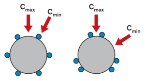
A linear ball bushing riding on a round shaft is often compared to a radial ball bearing, with the bushing acting as the outer race of the bearing and the shaft acting as the inner race. But in linear bushing assemblies, the surfaces of both the ball and the shaft are spherical, so contact between them is, theoretically, a point, meaning the resulting pressure between them would be infinite.
In real-world conditions, however, the surfaces of both the ball and the shaft experience some elastic deformation, resulting in an area (rather than a point) of contact between them. But this contact area is small, and the pressure between the ball and the shaft can still be extremely high and sufficient to initiate spalling and failure.
Because of the pressure created by the load-carrying balls, the hardness of the shaft plays an important role in determining the life of the assembly. Simply put, the harder the shaft surface, the better it can resist permanent deformation and avoid premature failure.
The hardness of bearing surfaces is typically quantified using the Rockwell C scale, abbreviated “HRC.”
To account for shaft hardness, life calculations for linear ball bushings include a shaft hardness factor (fH), which is applied to the dynamic load capacity (C). The shaft hardness factor is 1.0 for a shaft with hardness of HRC 60, but decreases for lower hardness values.
At a shaft hardness of HRC 60, the hardness correction factor is 1.0. Image credit: Thomson Industries Inc.
As shown in the life equation below, the shaft hardness factor (fH) is cubed, so it has a significant effect on the bearing life. In other words, if a linear ball bushing is used on a shaft of HRC 60 (fH = 1.0), it will have eight times (8x) the life of a bushing that is used on a shaft of HRC 50 (fH = 0.5).
Note that stainless steel shafts, which are commonly used in linear ball bushing assemblies, can have hardness ratings as low as HRC 54 (fH of approximately 0.7), depending on the grade of stainless steel. So linear ball bushing assemblies that use stainless steel shafts can have significantly lower life expectancies than those using standard HRC 60 shafts, even if all other operating parameters are the same.
Linear bearing shafts are typically hardened via induction hardening to a precisely controlled depth of anywhere from a fraction of a millimeter to several millimeters. The depth of hardening depends on both the diameter of the shaft and the shaft material, with larger diameter shafts requiring a larger hardness depth since they carry higher loads and experience higher pressures and stress concentrations.
Uniform depth in both the axial and circumferential directions is important to avoid uneven internal stresses. Image credit: Bosch Rexroth
Prior to machining, shafts that have been hardened require annealing — which involves controlled heating and cooling of the material — to reduce their hardness and make them workable. And it’s important to remember that high operating temperatures can reduce a material’s hardness. This is why the bearing life calculation for linear ball bearings often includes a temperature factor (ft), which de-rates the bearing’s dynamic load capacity for temperatures exceeding 100° C.
Check out this shaft material selector tool from LM76 for descriptions of different shaft materials and their suitability for use with linear ball bearings.
Designers of linear motion systems often find themselves weighing the pros and cons of round versus profile (also known as square) linear guides. Many considerations come into play while trying to determine which technology to implement; this is only further compounded when environmental extremes are a concern. Too often, the choice of linear guide technology is made late in the design process and based on assumptions. Taking time to perform a nuanced review can make the difference between a simple design and a complex one, affecting performance, assembly time and total cost.
The selection of round or profile (square) rails can make a difference in cost, performance and durability, depending on the application. Image courtesy of Thomson Industries
Round and profile rails are often interchangeable functionally, but there are marked differences even within those categories. Making the right choice for your application can spur significant advantages in cost, performance and durability. This article discusses how those differences play out in applications complicated by environmental extremes. Issues of fluid or solid particulate egress, temperature extremes, corrosion, shock and vibration design considerations will all be discussed.
Before going through these complicating factors, it is important to remember the pros and cons of both round and profile linear guides in an undemanding environment. Understanding these technologies and how they can be best applied to an application is always the first step in good design practice.
Round rails for forgiving installations
Round rail is the older of the two technologies and has been around for about 80 years. Typically, the most economical option (relative to component cost) round rails have a lower load capacity and looser accuracy. The design of the round rail is very forgiving; this forgiveness can be either a strength or a weakness depending on your application. For applications where loose tolerances are acceptable or where low component costs are more critical than tight tolerances, round rails are an excellent option.
Round rails are self-aligning and very forgiving of issues that arise from poor parallelism or variation in rail height for systems using more than one rail. This technology provides a smooth and low drag platform. The eloquently simplistic profile boosts highly effective sealing and a natural contamination resilience. In addition, round rails don’t need the time and expense of mounting surface machining and are the only option for end-supported applications.
Commonly used for hydraulic test benches, round rails position hydraulic pumps/motors for testing. The forgiving nature of the round guides make them the suitable choice for the application. Images courtesy of Motion Industries
Profile rail (also known as square rails) for tighter accuracy
Profile rail is the newer of the two technologies and has been around for about 40 years. Typically the more expensive of the two options, profiled rail has a higher load capacity and much tighter accuracy. The design of the profile rail isn’t forgiving, and this strictness can be of either great benefit to or a complicating factor for your design. The nature of this technology lends itself well to applications where extremely tight levels of precision are required, or where excessive loading is inherent to the task at hand. The compact nature of the system can help to reduce the overall size of the equipment, but higher preloads could increase in drag.
Further, the nature of the profile rail mounting and installation process (including surface machining) makes it very unforgiving of poor parallelism or variation in rail height for systems that use more than one rail. Manufacturing systems using profile rails need higher precision. Their elaborate, albeit compact, profile also suffers from more complex sealing and comparably poorer contamination resilience.
For a smelting plant application, this piece of an aluminum ingot handler utilizes profile (square) guides. Profile guides were selected because of the heavy load and high accuracy requirements. Image courtesy of Motion Industries
Fluid-exposure considerations when specifying linear rail
Exposure to fluids such as water, fog and high humidity can lead to corrosion of either rail type. Under pressure, as in washdown situations, fluids can wash lubrication away. Exposure to corrosive fluids such as chemical sprays, fuel oils, acidic food products, hydrocarbons, urea and fertilizers can introduce safety threats as well as contribute to wear, downtime and performance degradation. Both round and profile guides will differ in their fluid handling abilities based on sealing, lubrication type, material selection, coatings, mounting and standards compliance, which is particularly important in the medical and food industries.
For both round and profile guides, full-contact seals and proper lubrication will prevent rust from developing on the raceways of steel components. Seals on round guides tend to cause less drag due to their simple circular geometry, but low-drag options are available for profile rail assemblies. Profile rail carriages may also employ longitudinal seals that protect against ingress from the bottom of the assembly.
Material selection is another key component of the fluid handling ability of a system. Round rails have an advantage in that they can use non-hardened stainless-steel shafting. This makes them attractive for clean environments such as those found in the semiconductor and medical industries as well as the harsh environments of food processing. Higher loads may need hardened shafting. This can be accomplished with advanced coatings, which can extend component life 200-fold.
Coating options are comparable for both round and profile rails and in both cases, increased corrosion protection may involve tradeoffs with hardness. For example, Armaloy chromium coating provides moderate corrosion resistance and hardness of 78 HRc. In contrast, austenitic stainless steel such as 300 series is more corrosion resistant but more expensive — and has HRc hardness levels only in the 20s. Austenitic stainless steels are typically only recommended for use with plain-style bushings. Martensitic stainless steel, such as 440C, also offers improved corrosion resistance over carbon steel but can reach hardness levels in the 50s — and thus can be used with certain proprietary ball-bearing linear bushings.
In fact, other factors may come into play when considering coating options. Stainless steel, for example, is an especially good choice for food-grade environments or other applications in which users might be concerned about flaking off of the plating.
Well-chosen machine geometry, orientation, and guarding can also improve its ability to handle excessive fluid. Orienting the guide in a way that will minimize fluid penetration into bearing surfaces or that will promote runoff will also improve fluid handling. Profile rails are more compact, so they can provide more flexibility if standard mounting geometries are possible. The quality of the mounting surface finish is key to having the most flexibility during profile rail installations. To more facilitate installation flexibility, profile rails come in different mounting configurations. They can, for example, bolt from top or bottom and offer multiple methods to cover and protect bolt holes from debris, including cover strips, plastic rail plugs and metal rail plugs.
When more flexibility is required, round shafts have the advantage. They can be configured in many ways to facilitate holding the ends of the shaft and can even provide structural support in a larger assembly. Options to implement reduced diameters, flats or to drill through the case of the shaft, on center or radially, add to mounting flexibility. The self-aligning design of round rails is also more forgiving of poor parallelism and variations in rail height.
Safeguarding linear guides against solid particulate
Solid particulates such as metal, wood chips, extremely fine glass, ceramic dust or flour get into moving parts and impact wear and performance. Particulates can fall onto round or profile rails or may be airborne. Guide manufacturers address dust and particulate handling through sealing and wiper designs that protect against solid contaminants that land onto bearing surfaces.
Getting a robust seal on a profile rail is challenging because wipers must conform to the ball tracks which are ground in the rail and may increase drag — in fact, twice as much drag as with round linear bearings. Low-drag wiper designs for profile rail carriages help to minimize this problem but don’t eliminate it.
Profile rails might use scrapers to remove heavier particulate or bellows to shield raceways from any dust or particulate accumulation. Round rails have natural debris-shedding capabilities due to the curvature of their shafts. Although profile rail tracks are hidden from direct access, they don’t necessarily shed debris.
The equipment frame of this hydraulic test bench, which is finished and in use, protects the round rails from damage and contamination. Image courtesy of Motion Industries
How round and profile rail handle extreme temperatures
Extreme temperatures tend to have the greatest effect on plastic components, such as seals and recirculation mechanisms. Temperatures above or below the lubrication’s rating can cause components such as base oil, thickener and additives to separate and reduce. Fluctuations in temperatures can cause condensation, which leads to corrosion as well as thermal expansion and contraction in steel and aluminum.
Round rails can accommodate all-steel or stainless steel bearings with no plastic components. Both steel and stainless steel provide a wider operating temperature profile, but the stainless steel bearings have less load capacity than steel. Also, the plastic end caps and recirculation tubes in profile rail often prevent them from being used in extreme temperatures.
Vibration and shock resistance
Constant torque and movement can weaken a component over time and cause failure. Shock loading, as with an instantaneous impact load, affects all bearings. The heavier the load, the greater the problem, and because profile rails can handle heavier loads, shock is more of an impact force. In all cases, however, the rail is scaled to the capacity of the normal load and not to the shock load. The greatest impact is with heavy machinery, where the shock is more detrimental just because of the pure mass involved.
Profile rails are also more tolerant of heavy impacts because they offer various preload options, which can make them more resistant to other impacts that don’t affect the rolling element.
Round rails are less tolerant of impact due to their natural clearance fit. They do however outperform profile guides when a fluid driving force is applied to the rail because they are less likely to pull up on race areas than are profile rails.
Round or profile rail — the final verdict
The decision on whether to use round or profile rail depends on the application. As always, begin by establishing the motion profile and the essential performance characteristics. Then evaluate the options according to their advantages or disadvantages for each environment.
Profile and round rails can both be used in wet, corrosive, dusty and high shock and vibration environments, as long as the considerations are made for their design differences, accessories and overall precision and load requirements.
Where precision beyond the capability of round rails is essential in hazardous environments, coatings may be specified — or the designer will need to factor in the operational limits and incremental costs of the profile rails.
Profile rails may have some advantages in wet environments because their compact size provides more flexibility in mounting to avoid moisture, but if forgiving tolerances, nonstandard geometries or end-supported configurations are required, round rails have the clear advantage. There are many useful online tools available that help users weigh the tradeoffs among various hazardous conditions.
For more information, visit Motion Industries at MotionIndustries.com/designworld. Also watch this video on mounting options for round shafting …
About the authors
Lindsey Brimage is Product Line Specialist — Linear Bearings and Guides at Thomson Industries.
Lindsey supports the linear bearings and guides business while directing sales and customer support with technical product inquiries and training. She earned her Bachelor of Science in Chemical Engineering at the University of Pittsburgh and has worked at Thomson for two years.
Eric Schultz is Key Account Manager at Thomson Industries.
Eric develops and maintains strategic long-term relationships with key clients to collaborate on mutually beneficial projects, create solutions to meet objectives and support existing business. He earned his Bachelor of Science in General Engineering at the University of Illinois at Urbana-Champaign and has worked at Thomson for two years.
Based out of Calgary, Ian Miller, P. Eng. is National Services Business Development Manager of Motion Industries Canada.
He has more than a decade of hydraulic and electrical experience in the field including system design, troubleshooting, onsite installations, as well as technical training and support.
But linear ball bushings often experience operating conditions that aren’t accounted for in the general bearing life equation. To account for these adverse conditions, the life calculation for linear ball bushings includes a number of correction factors that adjust the bearing life accordingly.
Here, we’ll look at each of these correction factors and explain how and when to use them.
Load orientation
The load capacity of a linear ball bushing is maximized when the load is shared between two or more ball tracks. Image credit: Bosch Rexroth
The first correction factor (KΘ) accounts for the orientation of the load relative to the ball tracks, or circuits, in the linear bushing. When a load is applied to a linear bushing assembly, the orientation of the bushing on the shaft and the direction of loading determine whether the load is carried by just one ball track or shared between two or more tracks.
To account for this variability, manufacturers offer charts or polar graphs that provide load correction factors depending on the orientation of the load relative to the orientation of the ball tracks.
Note how the correction factor changes as the load moves from 0 to 360 degrees around the circumference of the linear bushing, relative to the orientation of the balls. Image credit: Thomson Linear
Unlike other correction factors, the load correction factor can be greater than 1.0 in some cases, meaning that a specific load-bushing orientation provides a dynamic load capacity that is higher than the published value.
Shaft hardness
In a recent article, we looked at how the hardness of the shaft can affect the life of a linear bushing assembly. Manufacturers typically recommend that shafts used with linear ball bushings have a hardness of 58 to 60 HRC. If the shaft hardness is lower than recommended, a shaft hardness factor (KS) must be applied to de-rate the bearing’s dynamic load capacity, and in turn, the bearing’s expected life.
Temperature
Very high operating temperatures can affect the integrity of the components that make up the bushing — such as seals and load plates — and can also reduce the shaft hardness. A temperature correction factor (KT) takes into account this degradation in material and typically comes into play for operating temperatures above 100° C.
Short stroke
When the stroke of a linear ball bushing is very short — between 1.5 and 3 times the length of the bushing, depending on the manufacturer and bearing type — the application is often considered a “short stroke” application. In these conditions, the shaft may experience accelerated wear and premature failure, since a small area of the shaft must continually withstand the forces and pressure created by the load-carrying balls. The short-stroke factor (KC) takes this into account and reduces the bearing life accordingly.
Life factor
The bearing life equation determines the expected life of linear ball bushing for a given dynamic load capacity and applied dynamic load. But in some cases, the desired bearing life and the applied load are known, and the parameter to be calculated is the required dynamic load capacity of the bushing that will provide the specified bearing life under the given load. In this case, the required dynamic load capacity (CR) is calculated as follows:
But recall that the bearing life for a linear ball bushing is based on 100,000 m (or 2 million inches for inch products). If the desired bearing life is greater than 100,000 m (or 2 million inches), the applied load must be divided by a life factor (KL) in order to account for the longer bearing life.
If you’re dealing with metric linear ball bushings, don’t forget to check whether the bearing is rated for 50,000 m or 100,000 m of life and apply the appropriate correction factor when making comparisons between bearings with different life ratings.
Gas springs, also called gas dampers, tension springs, gas-pressure springs depending on the setup and context, are compressed-air or oil cylinders that install in motion designs to damp forces and return kinematic linkages and more complicated assemblies to default positions. Gas springs work through a piston on the end of a rod that protrudes from a steel cylinder body; usually compressed gas (often nitrogen) within the cylinder exerts force on this piston to reassume and maintain set positions. Nitrogen is common here because it’s inert and nonflammable. In such designs, oil or grease between the piston and other contacting parts minimize friction.
Gas springs come in push-type and pull-type variations. If the design is setup as a tension spring, then what’s classified here as compression (retraction) is the extension position, and vice versa. The value difference between extension and compression forces for a give rod position is equal to the gas spring’s friction force.
This is an ACE Controls pull-type gas spring.
In fact, the small amount of oil in these gas springs serves another function — to further damp and gently decelerate gas springs during full extension or compression. Some setups even include a fine hole in the piston for damping that’s still slower than with other designs; such slow-damper springs are common on safety gates and doors.
In contrast, extended-reach gas springs usually leverage telescoping mechanisms pairing multiple cylinders on one rod; then the smaller cylinder extends from within the larger cylinder. Consider one particularly long-stroke application: Passive heave compensators — systems on ships or offshore oil-rig systems that reduce the effect of waves on engineered structures — use gas springs with strokes to many meters long.
Consider one example application of gas springs: As Wuhan, China became the first metropolis to confront COVID-19, crisis managers relied on mobile X-ray machines to quickly supply intensive-care physicians with imaging of patients’ lungs. Medical-imaging machine builder Beijing Wandong Medical Technology Co. supplied these machines.
The mobile X-ray machine has beam arm that’s adjustable to patient anatomy. The arm in turn uses a gas spring to hold its position without dropping on technologists or patients.
This is Wandong’s mobile X-ray machine.
When COVID-19 struck, Beijing Wandong suddenly needed a large quantity of springs to complete a rush order of the X-ray machines … so they turned to ACE Controls.
The mobile X-ray machine is 66.1 lb including its 22-lb beam arm. So in addition to the total weight, ACE Controls engineers had to account for the starting point (0°) and opening angle (130°) when choosing the specific gas spring.
Ultimately the engineering team chose GZ-28-450 pull-type gas springs — part of the component maker’s industrial gas-spring family. GZ-28-450 gas springs have a 1.10-in. OD, maximum force to 2,700 lb, at a stroke length of 17.72 in. — making them suitable for the mobile X-ray unit’s requirements.
The ACE Controls’ GS-28-450 pull-type gas spring provided a 270-lb traction force and low progression rate to hold the mobile X-ray beam arm in position and support raising and lowering motion.
The gas springs reliably hold the beam arm in position and provide assistance when imaging technologists raise and lower the arm … in contrast with push-type gas springs. More specifically, the gas pressure in the cylinder draws the piston rod in and supports the manual force needed for controlled motion when moving the arm. No matter the stroke length, the GZ-28-450’s traction force is adjustable thanks to a built-in relief valve.
Ultimately, ACE Controls industrial gas springs boost the safety and user-friendliness of Wandong mobile X-ray units.


 By
By 


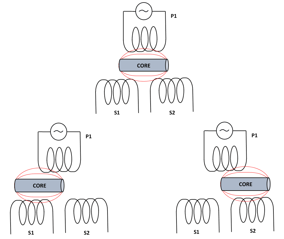
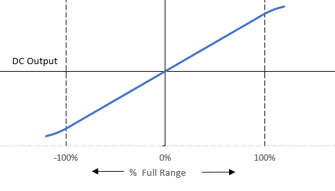


 High load capacity — play-free


 Athough scientists haven’t determined conclusively whether COVID-19 can be contracted by touching infected surfaces, the thought of touching communal surfaces such as door knobs and buttons can still be gross — even in non-pandemic times.
 One of the most effective ways to avoid contracting the virus that causes COVID-19 is to avoid touching your face. Unfortunately, most of us do it, and it’s a difficult habit to break. But the
  If the idea of wearing a wrist band isn’t appealing, the
  Another method to avoid contacting the virus is through
  Neck gaiters — cloth, mask-type face coverings — have received a bad reputation lately in terms of their ability to protect both you and others from the virus. But the
  Lego Hand Sanitizer Dispenser


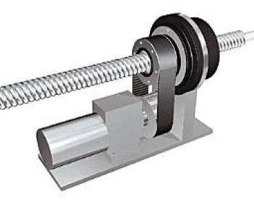
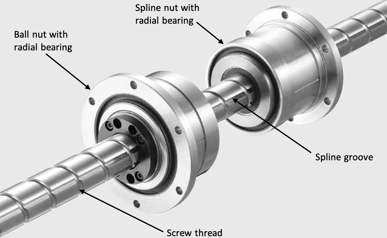
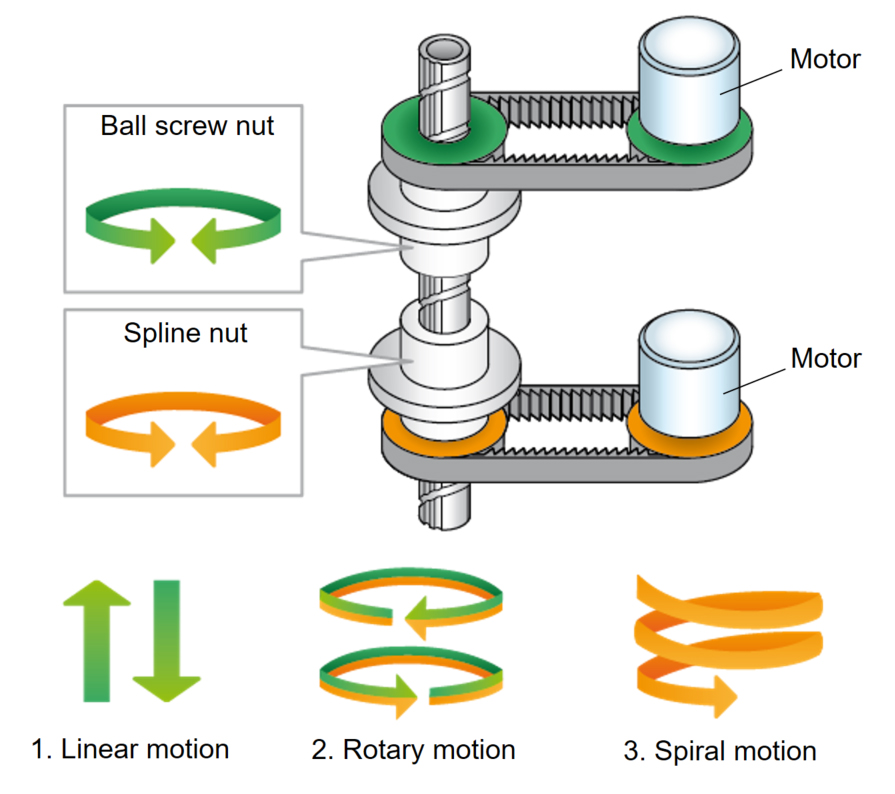


 A linear ball bushing riding on a round shaft is often compared to a radial ball bearing, with the bushing acting as the outer race of the bearing and the shaft acting as the inner race. But in linear bushing assemblies, the surfaces of both the ball and the shaft are spherical, so


 Based out of Calgary,
 Here, we’ll look at each of these correction factors and explain how and when to use them.