Consider the equipment that fills shampoo bottles. Such filling machines use conveyors to transport empty bottles to sensor-tracked wait positions. Then they insert shampoo-dispensing nozzles into the bottles and slowly raise those nozzles as the liquid rises during dispensing. Holding a constant distance between the nozzle ends and liquid surfaces prevents the shampoo from foaming.
After filling, the filled bottles continue onward to labeling and capping.
One plant employing such machines fills 10,000 bottles per day. Until recently, its machines included pneumatic cylinders to lower the dispensing nozzles to the fill-start bottle depth … and then raise them during filing until the nozzle tips exited the bottle openings.
Here’s the challenge: Shampoo dispenses from the nozzles at a constant rate … and the speed of liquid-surface rise is inconstant. The latter is unavoidable because narrower bottle portions fill more quickly than those with larger cross sections. So with the pneumatic system, the liquid rise speed would sometimes outpace nozzle ascent and submerge the nozzle tips — in turn causing (upon nozzle withdraw from the bottles) shampoo drips. These drips required cleanup of the bottle exteriors and conveyor.
There were a lot of problems with using pneumatic cylinders to lower shampoo-dispensing nozzles to the fill-start bottle depth and then raise them during filling. For starters, the nozzle tips often dribbled shampoo upon exiting the bottle openings.
Now the bottle-filing equipment uses electric actuators from IAI America for vertical nozzle motion. There are no shampoo drips to clean because the electric actuator continually adjusts its ascent speed to maintain a constant and optimal distance between the nozzles and liquid surfaces. That prevents the nozzles from inadvertently plunging into the liquid (and dripping shampoo upon exiting the bottle). Quality control is also higher as there are no more products rejected on the basis of being underweight due to the presence of bubbles. Finally, the elimination of cleanup saves the shampoo plant labor worth thousands of dollars per year. For more information, visit intelligentactuator.com.
Encoders that provide incremental position measurements (whether rotary or linear) output two signals, or channels, typically termed “A” and “B,” to provide position and direction information. These output signals can be in the form of analog sine and cosine waves or in the form of digital square waves. Those that produce digital output signals are typically referred to as simply “incremental encoders,” while those that produce analog output signals are referred to as “sine-cosine encoders.”
Incremental encoders for digital output signals
Incremental encoders can provide any of several types of digital output signals, but the two most common are high transistor logic (HTL) and and transistor-transistor logic (TTL).
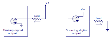
Incremental encoders with high transistor logic (HTL)output generate the output signal using two transistors in a totem-pole configuration. When the output is active, in the logic “high” state, the output voltage equals the supply voltage, so the transistors are “pushing” or “sourcing” the output signal to the load. When the output is off, or in the logic “low” state, the output voltage equals the supply common voltage level, in effect “pulling” or “sinking” the output signal from the load. This is why HTL output is sometimes referred to as “push-pull” output.
Sinking and sourcing are terms that refer to the direction that current flows when one signal is activating another signal. A sinking device provides a path for the current to ground and does not provide power to the device. A sourcing device provides power and “pushes” the current through the load. Image credit: circuitstoday.com
The supply voltage for HTL output encoders can range from 10 to 30 VDC, with 24 VDC being common. These encoders are often used when the controller requires a 12 or 24 V signal for the feedback input, or when the input voltage to the encoder is variable.
Incremental encoders with transistor-transistor logic (TTL)output provide a 5 VDC signal when the output is in the logic “high” state, regardless of the supply voltage, which can range from 4.5 to 5 VDC or from 10 to 30 VDC. When the output is in the logic “low” state, the output signal is 0 VDC.
TTL output uses differential wiring (A with /A and B with /B) to cancel noise.
Because TTL output encoders always use differential (complementary) signals, they’re sometimes referred to as “differential line drivers” or “balanced differential line drivers,” and are compliant with the RS422 standard when operated with a 5 VDC supply. TTL output encoders have very good noise immunity due to the differential signals, and so can operate reliably with long cable runs.
The term “line driver” refers to the fact that the circuit can source, or drive, current down the line, or signal cable.
Sine-cosine encoders for analog output signals
Output signals from an incremental encoder (top) versus a sine-cosine encoder (bottom). Image credit: Texas Instruments
Sine-cosine encoders are very similar to incremental encoders, except the output signals are 1 Vpp (Volt peak-to-peak) sine and cosine waves, rather than digital square wave pulses. The high quality of sin-cos signals allows high levels of interpolation, for better resolution and better control of position and speed.
In a type of encoding referred to as X4 encoding, resolution can be increased fourfold by counting the number of zero crossings of each waveform (sine and cosine) during each period. This type of encoding is also possible, — and common — with the digital output of incremental encoders, but because analog encoders use continuous sinusoidal waveforms rather than stepped, digital waveforms, the signals of sine-cosine encoders can be interpolated to a higher degree for better resolution.
Sine-cosine encoders are often used in servo systems, where high resolution is required for extremely accurate position and speed control. Analog output signals are, however, more prone to noise than digital signals, so it’s common for sine-cosine encoders to produce differential output signals to remove noise.
A high-power version of PI’s (Physik Instrumente) E-727 family of multi-axis piezo nanopositioning controllers provides 270 W of peak power – close to 10X of the standard version. The enhanced performance is useful for dynamic, nanometer-level precision motion and positioning applications, such as FSM (fast steering mirrors) in free space optical communication and laser material processing, and scanning stages for super-resolution microscopy, semiconductor manufacturing, automated photonics alignment or high-speed tracking applications. The E-727 high-speed digital servo allows for precision in the nanometer and sub-nanometer range with extremely fast settling in the millisecond range.
Advanced digital servo
The E-727 nanopositioning controller features an advanced digital servo providing significant advantages compared to conventional analog piezo nanopositioning controllers. Digital filters provide better linearity and higher bandwidth as well as on-the-fly parameter adaptation to changed loads or production requirements. Software-adjustable notch filters allow users to make full use of their piezo-mechanisms by suppressing mechanical resonances and yielding higher throughput and reducing step-and-settle times to milliseconds.
Other advanced features of the digital piezo nanopositioning controller include 4th-order polynomial linearization for both the piezo mechanisms and the electronics, an integrated data recorder, an ID chip for fast and quick exchange of the system components, as well as subordinate, programmable drift compensation. The dynamic performance can be further enhanced by a dynamic digital linearization (DDL) option. DDL reduces trajectory errors to an indiscernible level in the case of dynamic-periodic applications. This can improve the accuracy of high-speed scanning operations by several orders of magnitude, down to nanometer levels.
Interfaces and Software
The E-727 nanopositioning controller comes with USB, Ethernet, and even high-resolution 20-bit analog control interfaces. Like all PI motion controllers, it’s supported by LabVIEW drivers and dynamic libraries for Windows and Linux. An SPI interface provides high-speed serial data transmission.
Thomson Industries, Inc., has launched a new online selector tool that simplifies and streamlines the purchasing experience for its precision ball screws. The tool helps design engineers zero in on the right part quickly, access a 3D model with just a click, view pricing and lead times, easily share orderable product specifications and take advantage of direct online orders.
Ball screws, which are compact, quiet and cost effective, provide a low-friction, highly efficient technology for translating rotational motion to linear motion in many applications, including those involving high loads and close tolerances. A key offering in the Thomson portfolio of linear motion components, ball screws are available in metric, inch and miniature versions and can be configured as an assembly, which consists of a ball screw and ball nut with recirculating ball bearings. These assemblies are also featured in the ball screw selector tool.
“With multiple, ongoing machine design projects and frequent impending deadlines, motion systems design teams cannot afford to spend unnecessary time searching for the ideal ball screw for their applications,” said Denise Goldman, Global Product Line Manager – Ball Screws at Thomson. “We are focused on enhancing user experience and ensuring that they can swiftly identify the right ball screw in the least amount of time. This new tool enables them to complete the selection process in only a few minutes.”
To find the ideal ball screw for their application, users start by conducting their search through an intuitive, visual-based menu. They enter their application requirements and can narrow down their options to an optimal choice in just a few clicks. Further enhancements include real-time adjustments with defined filter parameters, and up-front pricing and delivery lead times. Another unique feature are product recommendations from Thomson engineers.
Users can also access new, verified 3D models, including ball screw assemblies, catalog links, and product details, all with a single click on the results page. The streamlined process not only takes significantly less time than traditional approaches, but it also yields better results.
The discrete, step-by-step movements that give a stepper motor its accurate positioning capability can also lead to some undesirable performance characteristics — namely, vibration and audible noise due to resonance.
Stepper motors naturally exhibit small vibrations with each step, due to the inertia of the moving rotor, which causes the motor to slightly overshoot (or, in some cases, undershoot) the step position and oscillate until it “settles” at the correct step angle. If the frequency of these oscillations matches the motor’s natural frequency, resonance occurs, which leads to audible noise, vibration, and — in extreme cases — lost steps or stalling.
While manufacturers use several design techniques to reduce resonance in stepper motors — such as special winding configurations or low-inertia rotor designs — there are also steps the user or OEM can take to reduce resonance in stepper motor systems.
The resonant frequency of a stepper motor (ω) is proportional to the square root of the motor’s torque stiffness (K) divided by its inertia (J). Changing either parameter will change the motor’s resonant frequency.
Reduce step size
The most widely recommended method to reduce stepper motor resonance is to make the motor’s step size smaller. This can be done through microstepping or by using a 5-phase stepper motor.
Microstepping is a control method for stepper motors that electronically divides each step into smaller increments. With smaller step sizes, the build-up and decay of current in each winding is more gradual and there’s less torque variance between steps. This means that position overshooting is less extreme, settling time is lower, and vibrations and noise are greatly reduced.
As step length decreases (i.e. microstepping), excitation energy – which can cause resonance – decreases. Image credit: New Japan Radio Co., Ltd.
Similarly, a 5-phase stepper motor reduces the motor’s step size by decreasing the offset between stator and rotor teeth to 1/10 of a tooth pitch, giving a step angle of 0.72 degrees (as compared to a step angle of 1.8 degrees for a standard 2-phase stepper motor). Again, the smaller step size means less torque is required for moving the rotor to the next position, so current build-up and decay are less extreme, and overshooting is reduced.
Add damping
Adding a mechanical damper is a simple way to reduce resonance in a stepper motor. Image credit: Lin Engineering
Mechanical dampers — whether internal viscous dampers or external damping devices — can eliminate or reduce stepper motor resonance by changing the inertia of the system, which in turn shifts the motor’s resonant frequency. And if the motor does experience resonance, dampers absorb some of the vibration energy that occurs as the motor oscillates and settles at the step position.
Use a gearbox
While gearboxes are typically used for increasing torque from the motor, the addition of a gearbox also increases the inertia of the motor side of the drive train, which reduces the motor’s resonant frequency (see equation above). Adding a gearbox to a stepper motor also means the motor will need to operate at higher speed — often outside its resonant frequency range.
The stepper motor with a gearbox (top) shows significantly less vibration than the non-geared stepper motor (bottom), especially at low speeds in the resonant frequency range. Image credit: Oriental Motor USA
Use a chopper drive
Another way to reduce stepper motor resonance is to precisely control the current to the motor so that it receives only the amount of current (and, therefore, torque) required for each step. This is often done with a type of stepper drive known as a chopper drive, which uses pulse-width-modulation to vary the output voltage and current to the motor and precisely control motor torque.
A ball spline is much like a linear ball bushing and shaft, but with axial grooves along the outer diameter of the shaft and the inner diameter of the nut. These grooves prevent rotation of the bearing (referred to as a spline nut) and allow the ball spline to transmit torque.
Because a ball spline has this unique ability to withstand both radial and torque loads, both loading conditions need to be analyzed when determining bearing life.
Since the load-bearing elements for both loading cases (radial and torque loads) are balls, the familiar bearing life equation can be used.
For a ball spline with radial loading, the bearing life is calculated as:
L = rated bearing life (m)
C = dynamic load rating (N)
P = applied radial load (N)
For a ball spline with torque loading, the bearing life is calculated in a similar way, but using the ball spline’s rated torque capacity and the applied torque load:
CT = dynamic torque rating (Nm)
T = applied torque (Nm)
Note that the life equations shown above are based on a life of 50,000 m (50 km). To convert these life ratings to a basis of 100,000 m (100 km), divide the 50,000 m ratings by 1.26, as explained here.
Like linear ball bushings, spline shafts sometimes encounter conditions that can adversely affect the bearing life, so the bearing life equation typically includes correction factors for shaft hardness, operating temperature, contact (to account for uneven loading when more than one spline nut is used on the same shaft), and shock and vibration loads.
These factors are often combined into a single “modification” factor:
f = combined modification factor
fH = shaft hardness factor (typically ranges from 0.5 to 1.0)
fT = temperature factor (typically ranges from 0.9 to 1.0)
fC = contact factor (typically ranges from 0.72 to 1.0)
fW = load factor for shocks and vibrations (typically ranges from 1.0 to 2.5)
With the correction factors, the life calculations become:
For radial loading:
For torque loading:
Note that the life calculations shown above assume that the radial and torque loads are applied in separate instances. If both radial and torque loads are applied simultaneously, the torque load should be converted to an equivalent radial load.
PE = equivalent radial load
i = number of rows under load
dp = ball circle diameter (mm)
cosα = contact angle
It’s important to note that this conversion is based on the number of rows that are under load, the diameter of the ball centers on the spline shaft, and the angle of contact, all of which depend on the unique geometry of each spline shaft and nut assembly, so these values must be provided by the manufacturer.
The geometry of the ball spline is important when converting torque loads to radial loads. Image credit: TBI Motion
With the equivalent radial load determined, the life equation for a ball spline with simultaneous radial and torque loading is given as:
Choosing a shaft for a traditional linear ball bushing is relatively easy — choose the appropriate diameter, material, and hardness, check the dimensional accuracies and tolerances, and if the shaft is unsupported, perform a beam deflection calculation.
But because spline shafts can withstand both radial and torque loads, it’s important to ensure the shaft strength is sufficient to withstand the applied bending and torsion moments and that the torsional rigidity is sufficient to keep the twisting angle of the shaft within permissible limits.
Required spline shaft diameter based on bending moment
The first step in analyzing spline shaft strength is to determine the shaft diameter necessary to withstand the applied bending moment.
The maximum applied bending moment equals the allowable bending stress multiplied by the shaft’s section modulus:
M = bending moment (N*mm)
σ = maximum allowable bending stress (N/mm2)
Z = section modulus (mm3)
Most shaft manufacturers provide the section modulus for each shaft type and diameter, so by solving this equation for the section modulus, Z, the appropriate shaft diameter to withstand the applied bending moment can be selected from the manufacturer’s catalog.
To find the required shaft diameter to withstand the applied bending moment, the equation can be rewritten as:
Required spline shaft diameter based on torsion moment
Because the spline shaft also experiences torque (twisting) loads, the shaft must have sufficient torsional strength to resist these loads.
The maximum applied torsion moment equals the allowable torsion stress multiplied by the shaft’s polar modulus:
T = torsion moment (N*mm)
τa = maximum allowable torsion stress (N/mm2)
Zp = polar modulus (mm3)
As with the section modulus (Z), above, most shaft manufacturers provide the polar modulus (also referred to as the torsion modulus) for each shaft type and diameter. so by solving this equation for the polar modulus, Zp, the appropriate shaft diameter to withstand the applied torsion moment can be selected from the manufacturer’s catalog
Otherwise, the torsion (polar) modulus for a solid shaft is equal to the polar moment of inertia divided by the shaft radius. For a solid shaft, the polar modulus is given as:
d = shaft diameter (mm)
To find the required shaft diameter to withstand the applied torsion moment, the equation can be rewritten as:
Special case: Simultaneous torsion and bending moments
It’s important to note that the cases above assume that bending and torsion moments are applied at different times. If they are applied simultaneously, the equivalent values for bending and torsional moments must be calculated, and these should be used in place of M and T in the equations above.
Equivalent bending moment:
Me = equivalent bending moment
Equivalent torsion moment:
Te = equivalent torsion moment
Torsional rigidity
Now that the shaft diameter has been selected, its torsion, or twisting, angle should be checked to ensure that it doesn’t exceed the manufacturer’s allowable limit, which is typically ¼° per meter of shaft length:
θ = torsion angle (°)
T = torsion moment (N*mm)
L = shaft length (mm)
G = shear modulus (N/mm2 = 7.9 x 10⁴ N/mm2 for steel shaft)
Ip = polar moment of inertia (mm4)
In addition to these calculations for shaft strength, the shaft deflection caused by radial loads should also be calculated and checked against the manufacturer’s maximum allowable value.
Outgassing can damage sensitive products such as semiconductor wafers, lenses, and microelectronic components. Image credit: WaferPro
Outgassing — the release of gas or vapor from a material through desorption, sublimation (the transition of a material from solid directly to gas), or evaporation — is a critical parameter for materials used in vacuum environments. These gasses and vapors can affect the pressure (or level of vacuum) in the vacuum chamber, and outgassed compounds can condense on surfaces, damaging or destroying sensitive components such as lenses, semiconductor wafers, and microelectronic components. Outgassing can also degrade sterile environments in medical and pharmaceutical applications.
A material’s level of outgassing is often determined using the ASTM E595 standard, which measures two parameters — “the change in mass of a test specimen on exposure under vacuum to a temperature of 125° C” (referred to as Total Mass Loss, or TML), and “the mass of those products that leave the specimen and condense on a collector at a temperature of 25° C” (referred to as Collected Volatile Condensable Materials, or CVCM).
An environment with a pressure less than atmospheric pressure (101,325 Pa or 760 Torr) is considered a vacuum, but vacuum environments are often broken down into five categories:
Image credit: Vac Aero
The most common units for specifying vacuum levels in industrial applications are:
Pascal, which is the SI unit (1 Pa = 1 N/m2)
Torr, which is used primarily in the U.S. (1 Torr = 1 mm Hg)
millibar (1 mbar = 0.001 bar; 1 mbar = 100 Pa)
Although the level of vacuum determines exactly what materials are suitable for a given application, there are some guidelines that serve as a good starting point.
For materials used in linear motion components, those that are generally discouraged from use in vacuum applications include:
Porous materials, including porous ceramics and metals
Anodized aluminum
Polyurethanes, rubbers
Nylon
Lubricants not specifically developed for vacuum applications
Outgassing is the release of gas or vapor from a material through desorption, sublimation, or evaporation. Image credit: Barnwell
Materials relevant to linear motion components that are generally acceptable in vacuum applications include:
Stainless steels (austenitic and some martensitic versions)
Non-anodized aluminum (especially well-suited for high vacuum)
Vacuum-rated, low vapor pressure lubricants and some solid lubricants
Fortunately, many linear motion components are offered with low outgassing materials as standard options or with readily available modifications.
Low outgassing linear guide options
Plain bearings have an advantage over ball and roller type bearings in vacuum applications because they don’t require lubrication, so one source of outgassing is automatically eliminated. And they’re available in a variety of plastic and composite materials that have low outgassing properties.
Plain linear bearings are offered in a wide range of materials with low outgassing, such as Frelon, a PTFE-based material used by PBC Linear, and some versions of iglidur material from igus. Image credit: PBC Linear
Ball and roller guides — whether crossed roller or recirculating types— are offered in a wide range of styles and sizes with all-stainless steel construction. Case in point: Crossed roller guides with metal cages and miniature profiled rail guides are commonly offered in all-stainless steel versions. And round shaft linear bushings are commonly available in all-metal versions, which can be made vacuum-compatible with proper bake-out (see below).
Standard profiled rails can be made with stainless steel and PEEK components for low outgassing. Image credit: IKO
For longer strokes with higher load capacities, some manufacturers offer all-stainless versions of standard (size 15 and above) ball and roller linear guides. And if a ball or roller guide style isn’t available in all-stainless, the standard plastic components — such as seals and recirculation end caps — can, in some cases, be replaced with vacuum-compatible materials such as PEEK.
Bake-out is a process that forces the release of trapped gasses and vapors in a material by heating the material to a high temperature (typically 200°C, although higher temperatures are sometimes required) while under high vacuum, for anywhere from several hours to several days. Performing a bake-out before using a product in a vacuum environment is standard practice for most levels of vacuum, and bake-out is mandatory for products used in ultrahigh vacuum (UHV) environments.
Low outgassing linear drives
For vacuum applications, screws and rack-and-pinion drives are typically chosen over belts, since common timing belt materials aren’t suitable for vacuum environments. Lead screws are especially well-suited for vacuum environments, since lead screw nuts can be made from PEEK and shafts are readily available in stainless steel. And like plain bearing linear guides, lead screws don’t require lubrication.
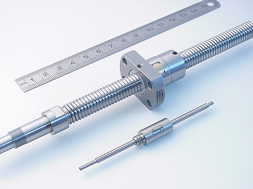
Lead screws and miniature ball screws are ideal for vacuum applications because they’re commonly offered in versions made of all stainless steel materials. Image credit: August Steinmeyer GmbH & Co.
Miniature ball screws are also commonly available in all-stainless versions, and some manufacturers offer standard ball screws in vacuum-prepared versions — with stainless steel materials and silicon nitride (ceramic) balls.
For nanopositioning, piezo motors can be made with low outgassing materials. Image credit: Newport
For nanopositioning, piezo actuators and piezo motors are readily available in low outgassing versions. It’s important to note that with any linear system, electrical and electronic components — such as motors, cables, and switches — also require special materials, since plastic connectors, soldering materials, and even encapsulation materials for motor windings can all contribute to outgassing.
Lead screw manufacturers offer nuts in a wide array of materials, including various plastics and grades of bronze. And while plastics garner a lot of attention for their versatility and range of suitable applications, lead screw nuts made of bronze are especially well-suited for applications with high loads or extremely high (or low) temperatures.
Plastic nuts are available in dozens of formulations, from materials such as acetal (Delrin), PEEK, and nylon, to materials that are proprietary to certain manufacturers, such as the range of plastics marketed as iglidur by igus.
Custom lead screw nuts made of plastic. Image credit: igus
Bronze nuts are typically made of bearing-grade bronze such as SAE 660 (C93200), although other grades are available from some manufacturers.
Bronze lead screw nuts are typically made from bearing-grade material, such as SAE 660. Image credit: Abssac
When a bronze lead screw nut is the best choice
In a lead screw assembly, the nut plays a primary role in determining several performance characteristics, including load capacity, where bronze holds a significant advantage over plastics. This is because bronze can withstand higher loads — including thrust loads — and has better resistance to impact and shock loading than most plastics. However, lead screw nuts made of bronze generally have a higher coefficient of friction than nuts made of plastic, so they generate more heat and may not be suitable in applications with high loads and high duty cycles.
Lead screw nuts made of bronze are better suited for high load capacity and high (or low) temperature applications than plastic versions. Image credit: Thomson
Bronze nuts are also better suited than plastic versions for corrosive and for high (or low) temperature environments. A bronze nut paired with a stainless steel screw offers good corrosion resistance for most liquid contaminants, and this combination is often used in food and beverage applications. Bronze nuts also have a wider range of operating temperatures than most plastic versions. (Keep in mind that the lubrication used with the bronze nut should also be able to withstand the extreme temperature conditions.)
Can you use PV factor to select a bronze lead screw nut?
Because plain bearings rely on sliding friction, rather than rolling friction like ball and roller bearings, the standard L10 bearing life equation doesn’t apply to plain bearings. Instead, the suitability of a plain bearing for a particular application is often evaluated by the bearing’s PV (pressure x velocity) value. But the PV equation was developed for plastic materials, whose wear characteristics don’t depend on lubrication.
However, any metal-on-metal sliding or rolling contact, such as a bronze nut on a steel or stainless steel screw shaft, requires lubrication. The type and amount of lubrication affects the coefficient of friction between the nut and the screw, and therefore, the wear characteristics of the nut. So for lead screw assemblies that use bronze nuts, the PV value is only somewhat useful as an indicator of the nut’s suitability for a specific application.
To address this, some manufacturers have conducted empirical testing to create modified PV charts for bronze nuts. These modified charts include a third parameter to address how often the screw assembly operates and under what lubrication conditions.
To address the role that lubrication and duty cycle play in the wear of a bronze lead screw nut, some manufacturers have developed modified PV charts for bronze nuts. In Area A, continuous operation is acceptable. Area B allows limited operation with constant lubrication. Area C allows only intermittent operation, even with constant lubrication. Image credit: Automation Components Ltd.
The capacity of a mechanical system to sustain external loads without excessive changes of its geometry (deformations).
When we think of stiffness in traditional bearings with rolling elements, we’re typically considering the deflection of the carriage when a load is applied. For air bearings, which use a thin film of pressurized air to support the load, stiffness represents the bearing’s ability to maintain a consistent air gap — in other words, to resist changes in the air gap due to compression of the air caused by an applied load.
Air bearing stiffness is the derivative of the bearing’s load capacity versus the air gap thickness (lift). Image credit: New Way Air Bearings
Because air is a compressible medium, any change in loading will change the thickness of an air film between two surfaces — for air bearings, this means that an increase in load will cause a decrease in the air gap, due to the compression of air. Thicker air gaps are more compressible than thinner air gaps, so air bearings that are designed for high stiffness typically operate with extremely small air gaps, on the order of a few microns.
As the load on an air bearing increases (within the bearing’s rated load capacity), stiffness also increases. Image credit: Roger Cortesi, MIT
In addition to the size of the gap, another factor that affects air bearing stiffness is compensation, which is the method by which airflow into the air gap is controlled. Compensation works to create a restriction of airflow thru the orifice and into the gap, before the restriction of the gap itself. This restriction provides a restoring force when a load is applied or increased, allowing the bearing to resist compression of the air gap due to the increased load. In other words, the restricted airflow through the orifice provides “reserve” pressure that can maintain the air gap when external forces attempt to compress it.
With no mechanical elements to generate friction or heat, air bearings – and air bearing stages, like the one shown here – are ideal for applications that require extremely high precision and stiffness. Image credit: Aerotech Inc.
Like rolling element linear guides, air bearings can also be designed with preload to increase stiffness. There are several methods for creating preload on an air bearing: adding mass (weight), applying a vacuum to the air bearing, installing magnets on the moving and stationary parts, and combining two opposing bearings to create preload between them. Regardless of the preloading method, the result is the same: as a load is added to the bearing, the air gap compresses and the pressure increases, and so does the stiffness of the air film.
While it’s difficult to compare the stiffness of an air bearing with a rolling element bearing (due to functional and size differences), it’s important to note that the air film supporting the load in an air bearing provides a continuous area of support. In contrast, rolling element bearings — whether they use balls or rollers – rely on multiple, very small areas of contact to support the load. And the stiffness of a rolling contact bearing depends on several non-linear factors that are difficult to model or predict, whereas air bearings have very predictable, linear stiffness characteristics.
Linear position feedback devices — also referred to as linear encoders — typically measure travel distances ranging from a few dozen millimeters to several meters. But when a positioning system has a very short travel — a few millimeters or less — traditional linear encoders are often too bulky or don’t provide the required measuring resolution. For these applications, capacitive sensors offer a compact solution that can measure position with nanometer-level resolution.
Rather than a scale and a read head, like typical optical and magnetic linear encoders, capacitive sensors are typically made from two metal plates with a dielectric, or insulating layer, between them — a design referred to as a parallel plate capacitor.
A capacitor is a device that stores electrical energy, and capacitance is a measure of how much charge the capacitor can hold. For parallel plate capacitors, capacitance depends on three factors: the overlapping area of the plates, the permittivity of the dielectric between them (typically air), and the distance between the plates.
When a voltage is applied to a parallel plate capacitor, a positive charge accumulates on one plate, and a corresponding negative charge accumulates on the other plate, creating an electric field between the plates. This field is monitored for changes, which indicate a change in capacitance.
Any change in the electrical field between the two plates indicates a change in their overlap or a change in the distance between them. Image credit: AspenCore
Because the dielectric separating the plates does not change, any change in capacitance is due to a change in geometry: either a change in the overlapping area of the plates or a change in the distance between them. A change in the overlapping area, “A,” indicates a change in planar displacement (movement of the plates relative to one another along parallel planes), whereas a change in the distance, “d,” indicates a change in axial displacement.
In most applications, one plate is made stationary and the other plate is attached to the object being moved, and the plates are arranged so that their overlapping area does not change. Therefore, any change in capacitance is a result of a change in the spacing between the plates and represents the distance that the moving object has traveled.
Capacitive sensors — also referred to as capacitive displacement sensors — are absolute position measuring devices, and since they measure the position of the moving part directly, linear and planar errors are eliminated, giving them very high accuracy with resolution in the nanometer — or in some cases, sub-nanometer — range. One example of their use is in optical inspection equipment, where the features being measured are at the sub-micron, or nanometer, level. Here, capacitive sensors are used to ensure the correct distance is maintained between the part and the measuring optics.
Because they can measure small distances and have very compact dimensions, capacitive sensors are often used in micro- and nanopositioning systems based on piezo motors or voice coil actuators. However, they’re not suitable for humid or wet environments, or those with significant temperature changes, since water has a different dielectric constant than air and can change the permittivity (ε) of the capacitor.
The transition of mobile machinery and off-highway equipment away from fossil fuels may be a long-term goal, but electrification is already delivering real benefits in the sector.
Is the era of the internal combustion engine coming to end? Under pressure to reduce harmful emissions, the automotive industry is already gearing up for a large-scale transition to electric power. Now attention is turning to other mobile machinery applications — especially the types of heavy-duty equipment widely used in agriculture, forestry, construction and municipal roles.
In one survey of the mobile machinery sector, more than 70% of respondents said they thought electric power would eventually become more prominent than fossil-fuel power. More than 86% said that electrification is already becoming a more important topic for their organizations.
But despite the growing interest in the topic, real progress in the electrification of mobile machinery has been slow. More than 40% of respondents to the same industry survey said that electrification hadn’t yet impacted their companies.
Agriculture equipment benefits from better function adjustments using electromechanical actuators to replace hydraulics. Designed to operate in temperatures from -40 to 85°C at up to 20% duty cycle, Ewellix CAHB 20E, 21E and 22E actuators feature robust metal gears, high holding force, speeds to 55 mm/sec, mechanical over-load protection, and a manual override option.
Barriers to wholesale electrification include the high cost and limited availability of batteries with sufficient capacity to support demanding real-world operating cycles. In some sectors, access to suitable charging infrastructure can be another important issue.
Baby steps to incorporate electric actuation
However, machine builders and end users are increasingly recognizing that even partial electrification of equipment offers significant cost, reliability, and operational benefits. In off-highway designs, that’s driving renewed interest in hybrid architectures involving a combustion engine to generate electric power for the machine — sometimes in combination with onboard battery storage. Here, the power takeoff from the engine or the hydraulic output can be replaced by an electrical output. That in turn allows use of electromechanical actuators as a real alternative to the hydraulic systems that have dominated the mobile machinery sector for decades — especially in applications necessitating high loads.
Electric drivetrains have become the standard in forklift trucks used indoors or in warehouses. To improve runtime, the efficiency of its work or steering functions can be improved by employing electromechanical actuators, such as the Ewellix CASM-100.
Let’s look at those potential benefits in detail. First, there’s efficiency and stability. Electromechanical systems only consume the requested energy per cylinder or actuator when they’re actually moving an axis, and they can be up to 80% efficient in turning input power into useful work. That’s in stark contrast to the 44% end-to-end efficiency of a typical hydraulic power system. Greater energy efficiency means lower CO2 emissions … and represents significant cost savings for operators.
For internal combustion engine vehicles, the fuel costs of fully electromechanical mobile machines can be half those of their diesel-powered counterparts.
Electromechanical actuators such as the CAHB can be connected to the battery of vehicles to easily integrate higher comfort functions, such as tipping in a UTV.
For battery electric vehicles, the batteries on board can be halved in size and accept quicker charging. In addition, the recovery of electricity increases the efficiency even further … enabling a reduction in battery costs.
Off-highway equipment use of electric systems can offer other environmental advantages too. Machines with onboard energy storage can be designed to operate under electric power alone for parts of their operating cycle. That makes them much quieter … a real benefit for equipment operating overnight in urban areas, for example. Plus because electromechanical systems don’t use high-pressure oil, the risk of accidents or pollution from fluid leaks is eliminated. That’s a boon for vehicles working in the cities or in clean indoor spaces, but also for agricultural machines and for any equipment that operates in sensitive natural environments.
Several performance premiums with electric actuation
Another consideration is the cost of keeping equipment running. Modern electromechanical actuators offer very high levels of reliability and long operating lifecycles with very little requirement for routine maintenance. Even if an actuator does fail in service, replacement is usually a simple case of swapping the component and connecting a few cables. In contrast, hydraulic systems unfortunately require specialist maintenance expertise and can incur extensive downtime.
Off-highway equipment use of electric systems also boosts productivity. The speed, position, and acceleration of electromechanical actuators can be precisely controlled over their full range of motion, without the need for elaborate additional control equipment. That capability boosts machine performance and is key to new generations of smart machines that must satisfy wider ranges of tasks and operating conditions than in the past — or must dynamically adapt output as commanded by machine controls. The communications cabling between these electronic controls and electromechanical actuators employed on off-highway equipment are usually via simple I/O or some bus communications such as CAN bus.
Ewellix’s CASM-100 modular electric cylinder platform is a line of modular (customizable) actuators developed to address a wide range of heavy machinery applications. Several options are available, making CASM-100 actuators suitable replacements for hydraulics on high-load axes — even those needing up to eight tons of force over medium to high duty cycles. Another benefit is how CASM-100 electromechanical actuators allow regeneration of electric power on vertical axes during the lowering of the load, challenging to accomplish with hydraulic systems.
This connectivity imparts industrial internet of things (IIoT) capabilities in electromechanical actuators — so OEM machine builders and operators get:
• Straightforward access to high-quality data relevant to fleet monitoring and predictive and condition-based maintenance approaches
• Access to real-time data for onboard diagnostics — a key requirement of autonomous vehicles or robots needing self-reliant systems
This IIoT connectivity is possible without the addition of complicated sensor systems needed to collect performance data from hydraulic or pneumatic systems.
Ewellix electromechanical actuators can be used in applications requiring oil-free operation or demanding higher energy efficiency, with added benefits of integrated sensors and telematics connectivity.
Migrating mobile machinery to electromechanical linear actuators
Many of today’s electric-actuator offerings for mobile equipment trace their roots to designs that have been used for decades on road pavers, road sweepers, combine harvesters, lawn mowers, and other work vehicles needing auxiliary adjustment or lifting systems. What’s new is that designing and specifying electromechanical systems in mobile machinery has in recent years become increasingly straightforward.
Most all of these actuators have at their core a dc motor for easy integration into battery-powered and onboard power-generation systems.
Most all of these actuators also have ruggedized and sealed bodies to withstand wild operating temperatures and corrosive outdoor settings.
Ewellix CAHB22E linear actuators are suitable maintenance-free replacements for pneumatic or light hydraulic cylinders with 32 mm or 40 mm bores in medium-duty-cycle applications. Rated to IP66M/69K (and sealed by a vent) the self-locking actuators deliver push forces to 10,000 N and pull forces to 20,000 N.
Beyond that, electric-actuator features are fairly flexible … with some suppliers of electromechanical systems offering highly modular designs to let OEMs tailor performance features to their build in a cost-effective and well-integrated package. Some such actuator manufacturers even provide OEMs additional assistance in this design process … by leveraging years of development, testing, and customer-support experience to help engineer actuator systems specifically designed to satisfy the rigors of mobile applications.
On a related note is a relatively new development in industry — namely, the availability of modular actuators for which heavy-machinery builders can even specify base component features and internal components. These actuators essentially serve as custom-like stock solutions with optimized performance-to-cost ratios.
Ewellix, headquartered in Gothenburg, Sweden, is a global innovator and manufacturer of Linear Motion and Actuation solutions used in industrial automation, medical applications, mobile machinery and distribution. Formerly part of SKF Group, the Ewellix Group employs about 1,400 people and consists of 16 sales units and nine factories. External net sales are approximately 2.3 SEK billion.
The first step in any automation project is to clearly define the objective — what process are you trying to accomplish or what output are you trying to produce? Once the process or output is defined, it’s time to dig into the details of the application so you can choose the right components or systems to achieve the desired result in the most efficient, cost-effective way. Documenting the application parameters will also help you communicate specific requirements to vendors and integrators.
To define a linear motion application, start with three fundamental questions:
What are you moving?
How far are you moving it?
How fast does it need to get there?
Here, the question of “What” refers to the type of load being moved — its mass, shape, and size. Also define where and how the load is oriented relative to the linear motion system, and whether any of these parameters changes significantly during the process.
In addition to the size, shape, and mass of the load, its orientation relative to the linear system is also an important parameter for sizing. Image credit: Rollon
Keep in mind that some applications also include axial (pressing) loads, and these need to be considered during the sizing and selection of drive components. And if the load orientation is vertical or inclined, special circumstances need to be taken into account, such as buckling forces on the drive mechanism and the potential for the load to back drive (or worse, for the load to “drop”) if power is lost.
“How far” means the stroke, or travel length, and whether there are any intermediate stops or changes in the stroke over the course of the process. The question of “how far” also leads to precision — defined as positioning accuracy and repeatability, as well as travel accuracy requirements.
Along with stroke, or travel length, be sure to define the requirements for positioning accuracy, repeatability, and travel accuracy.
“How fast” refers to the move profile of the stroke. The goal might be to move the load to the target position as quickly as possible, but most applications have specific requirements for traveling at constant velocity during part of the move, for dwell time, or even for maximum speed or acceleration due to the nature of the load or safety concerns. The move profile will also determine the required torque and speed from the motor and whether the application requires a gear reducer.
The move profile should take into account maximum speed, constant velocity, maximum acceleration and deceleration, and dwell time. Image credit: Varedan Technologies
When defining the move profile, the duty cycle should also be defined. In other words, how often will the move be made — how many times per minute, hour, or day? The duty cycle affects not only the life of moving components, it also affects the amount of heating the motor will experience during operation and can have a significant influence on motor selection.
Be aware that although these three questions — and the application parameters related to them — cover the main performance requirements of a linear motion system, there are other factors that need to be taken into account as well. For example, any special environmental conditions that the system needs to withstand — such as extreme temperature, cleanroom or vacuum, or contamination — should be defined at the initial stages of sizing and selection, as these can be a determining factor in regards to which components or systems are acceptable.
Fortunately, manufacturers of linear motion components understand that sizing and selecting their products can be a complicated and intimidating process. To help designers and engineers with defining the application, several manufacturers have come up with catchy acronyms that spell out the application parameters required for sizing. Here are a few examples:
Bosch Rexroth was the first to develop and promote an acronym that describes the information required for sizing a linear motion system, and these seven parameters are still the foundation of any linear motion sizing project.
Rollon makes the case that time and budget should also be included — because what good is a solution if it doesn’t fit within your budget or can’t be delivered within the required timeframe?
Accuracy Capacity Travel Length Usage (aka duty cycle) Ambient environment Timing (aka time and budget) Orientation Rates (aka move profile)
PBC Linear has added two criteria — unknown and safety — and formed an entirely new acronym.
Precision Orientation Speed Travel Load Unknown (What are the “known unknowns?” What could go wrong?) Duty Cycle Environment Safety
Regardless of which acronym you use — or whether you come up with your own catchy acronym or mnemonic device — remember that the more information you can provide regarding the application, the more likely you are to get a linear motion system that exactly meets the application requirements, without being oversized or undersized.
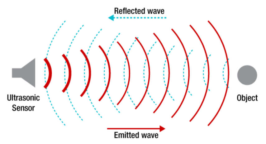
In nature, some animals — such as bats and dolphins — analyze the echo of a sound or call (a process known as echolocation) to navigate or to find prey. In industrial applications, ultrasonic sensors use the analysis of echos from ultrasonic waves to determine the presence, position, or distance of an object.
By analyzing the echos of a ultrasonic waves, ultrasonic sensors can determine the presence, position, or distance of an object. Image credit: Texas Instruments
Ultrasonic waves are sound waves emitted at a frequency higher than can be detected by human hearing — typically above 20 kHz.
Ultrasonic sensors use piezo ceramics to emit and receive ultrasonic waves, converting electrical energy to acoustic energy during transmission and then acoustic energy back to electrical energy during receiving. By analyzing the timing, distortion, or absence of the echo, ultrasonic sensors can detect the presence or position of an object or measure the distance to a target object.
Ultrasonic sensors for industrial applications generally come in three varieties: diffuse mode, retroreflective, and thru-beam.
Diffuse mode is the most common type of ultrasonic sensor, using a single transducer to both emit and receive the ultrasonic waves. A simple formula allows the object’s distance from the transducer to be calculated:
d = distance to object, one-way (m)
c = speed of sound in specified medium (m/s)
t = time between emission and reception, also referred to as “time of flight” (s)
Retroreflective mode is similar in that it uses only one transducer to both send and receive, but in retroreflective mode, ultrasonic waves are constantly reflected to the transducer by a separately-installed reference reflector. When there’s no object between the sensor and the reference reflector, the sensor receives a constant echo from the reflector. But if an object enters the sensing range, the reflection of the echo wave changes, and the sensor detects the object’s presence by the change in the echo. This mode is often used when the object to be detected absorbs sound or when its surface is not easily detectible, such as very smooth or slanted surfaces.
Unlike diffuse mode and retroreflective types, thru-beam ultrasonic sensors use separate devices for transmitting and receiving the ultrasonic waves. Image credit: Baumer
For thru-beam mode, the emitter and receiver are separate devices mounted opposite one another along a common axis. When an object disrupts the ultrasonic waves between the emitter and receiver, an output signal is activated. Thru-beam ultrasonic sensors have double the detection range of a typical diffuse mode or retroreflective sensor. Their switching frequency can also be much faster than other types.
When a single transducer is used as both the transmitter and receiver, it experiences a blind zone — an area in front of the sensor where objects cannot be detected. This is because the sensor cannot transmit and receive at the same time. The size of the blind zone is determined by how long it takes for the resonant energy from transmission to dissipate.
The blind zone is an area in front of the sensor where an object cannot be detected. Image credit: Pepperl+Fuchs
Because thru-beam type sensors use separate devices for transmitting and receiving, they don’t experience a blind zone.
Output can be an analog voltage or current value that varies proportionally with the measured distance, a digital value representing position, or a switching output for on/off operation.
Sensor output can be an analog current signal proportional to the measured distance. Image credit: Senix
Ultrasonic sensors work for almost any kind of target medium, including powders and liquids and objects that are transparent, have a high-gloss finish, or that change color. However, materials that are absorbent — such as wool, cotton, or foam — reduce the sensing distance and accuracy. Ultrasonic sensors are also resistant to most disturbances that affect other types of sensors, such as vibration, ambient noise, dust, smoke, or mist. And some manufacturers offer designs that are sealed in a stainless steel housing, so they can be used in aggressive environments and fulfill hygiene requirements for food and beverage applications.
Sensing range depends on the surface properties and the angle of the object to be detected, but can typically reach several meters, with resolution in the range of 0.1 mm and absolute accuracy (accuracy of distance measurement to a non-moving object) of 1 to 3 percent. The longest sensing ranges are achieved for surfaces that are flat and positioned at an exact right angle to the sensor.
Because they rely on the “time of flight” of ultrasonic waves, ultrasonic sensors are sensitive to environmental factors that affect the speed at which the waves travel. For example, air temperature* can have a significant effect on the accuracy of ultrasonic sensors, so they typically include temperature probes and compensation algorithms. And at high temperatures, the speed of sound in air is affected by humidity, with speed increasing as humidity increases.
*The speed of sound in air is approximately 343 m/s at 20° C, but changes by 0.175 percent per degree C.
Both LVDTs (linear variable differential transformers) and resolvers are measuring devices that convert displacement into an electrical signal. As its name implies, an LVDT is used for linear measurement, while a resolver is used to measure rotary, or angular, displacement.
In terms of construction and operation, the most significant similarity between an LVDT and a resolver is that they are both transformer-based measuring devices, meaning they use electromagnetic induction to transfer, or induce, voltage from a primary winding to secondary windings.
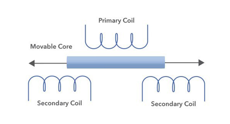
An LVDT contains a primary winding and two secondary windings wound around a hollow form. A ferromagnetic core sits inside the bore and travels back and forth along the windings. Image credit: Honeywell International
An LVDT has three windings — a primary winding and two secondary windings — wound around a hollow form. The primary winding is located between the two secondary windings, and the secondary windings are wound in series but in opposite directions. These three windings make up the transformer. Housed inside the bore of the transformer is a ferromagnetic core, which can move freely along the internal bore. This core is attached to the part being measured via a non-magnetic shaft, or push rod.
When a voltage is applied to the primary winding, magnetic flux is produced and couples to the secondary windings via the ferromagnetic core. This magnetic flux induces a voltage in each of the secondary windings.
LVDTs and resolvers are both transformer-based measuring devices that rely on electromagnetic induction to induce from a primary winding to the secondary windings. Image credit: United Electronic Industries
The location of the core with respect to each of the secondary windings determines the amount of voltage induced in each, and the differential voltage output between the two secondary windings determines the distance moved. The direction of movement is determined by the whether the output voltage is in phase or out of phase with the primary voltage.
A resolver is also a transformer-based device, using three windings — a reference winding on the rotor (which is attached to the component whose position is being measured, such as a motor shaft) and two secondary windings on the stator. The stator windings are mechanically oriented at 90 degrees to each other (in quadrature) and are referred to as the sine and cosine windings.
A resolver contains a rotor with a primary winding and a stator with two secondary windings (SIN and COS) arranged 90 degrees apart. Voltage is supplied the primary winding by a rotary transformer. Image credit: Advanced Micro Controls, Inc.
For brushless resolvers, voltage is supplied to the reference winding on the rotor by a rotary transformer, which induces voltages in the secondary windings on the stator. The induced stator voltages are equal to the reference voltage multiplied by the sine and cosine (respectively) of the input shaft angle from a defined zero point.
The precise shaft position is determined by taking the ratio of the voltages in the secondary windings, and the direction of rotation is determined by which signal (sine or cosine) is leading.
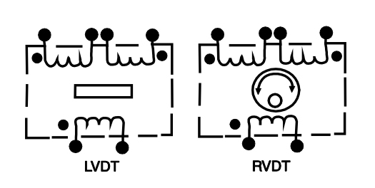
Another transformer-based device to measure rotary displacement is the rotary variable differential transformer (RVDT). An RVDT operates much like an LVDT, with a ferromagnetic core, one primary winding, and two secondary windings. The secondary windings are wound 180 degrees out of phase. But in the case of an RVDT, the shaft acts as the core and the windings are located on the stationary part of the assembly.
The main difference between an LVDT and and RVDT is the core. Image credit: Data Device Company
When voltage is applied to the primary winding, the core induces voltages in each of the secondary windings. These voltages vary linearly with the angular position of the shaft (core), and the differential voltage output determines the angular position of the shaft. Similar to an LVDT, the direction of movement (rotation, in this case) is determined by the phase difference between the output voltage and the reference (input) voltage.
A disadvantage of rotary variable differential transformers is that their measuring capability is linear over a limited range — typically ±40 degrees of rotation, although some designs can be used for up to ±70 degrees of rotation.
Pneumatic actuation has long been a tried-and-true motion method in many industries and applications. But today’s pneumatics companies are not your grandfather’s pneumatics – they are changing along with broader industrial and manufacturing trends, and continue to evolve their product offerings in line with new industry demands.
Fluid power actuation, like pneumatics, is not going away. But it is evolving. Case in point; servo pneumatics. As Frank Langro, Director of Product Market Management for Pneumatic Automation at Festo North America, points out, “the servo pneumatic application range has narrowed as the cost and ease-of-use of servo electrics has become more economical.” He cites the company’s Simplified Motion Series of low-cost electric actuators as an example of electric motion becoming interchangeable with pneumatics in simple two and three position applications.
The EXCM mini planar surface gantry from Festo integrates a number of actuation methods, including a recirculating toothed belt moved by two electric motors, as well as a pneumatic slide.
Still, proportional pneumatic solutions are not going away. As Langro points out, “servo press, for example, is an area where servo pneumatics deliver the price and performance that is ideal for the application. Intelligent pneumatics such as the Festo flexible valve VTEM, which changes functionality via downloadable apps, utilizes servo pneumatic control in a host of various ways to provide OEMs with new solutions for improved performance.”
Pneumatics manufacturers are also seeing changing demand from different industries. Tim Sharkey, Director of Product Market Management for Electric Automation at Festo North America, says that he’s seen warehouse and distribution centers pushing the automation envelope. “Some of the motion innovations developed for warehouse/distribution will be useful in other applications benefiting from smart, flexible material handling and mobile automation,” says Sharkey. Examples of other applications include meat processing, especially with the effects of the coronavirus impacting worker density and the need to increase space between workers. The farm industry may also be on the cusp of further automation, although some significant technology hurdles remain, including motion, vision, AI, and cost issues.
There is also increased demand for miniaturization and even integration of feedback devices into many linear components, especially with the trend toward smart manufacturing. “Smart manufacturing implies that more information about the machine’s condition and operation is available,” says Langro. “With the Festo SDAT position transmitter, for example, the controller has data on the actual distance traveled by the cylinder. Minute changes in the length of extension may indicate that the cylinder requires maintenance or replacement, a part may be damaged, or the part does not meet quality specifications.”
Stainless steel cylinders like those offered by Festo feature resistance to surface corrosion, pitting, and crevice corrosion and are well-suited for use in harsh environments.
Smart manufacturing capabilities like these contrast with a situation where there is no insight into a manufacturing process. Here, for instance, a maintenance technician at the end of a shift may have to examine a bad batch of product, trying to determine the root cause of a failure. With smart manufacturing, greater insight into processes can improve competitiveness.
What’s more, there’s a trend toward an increased demand for absolute encoders, spotlighting one of their key advantages; “during a power loss or with an external force applied, the system is capable of moving the load. The servo system will already know its position rather than performing a homing routine,” notes Sharkey.
The addition of a linear feedback device on the actuator plus one on the motor is another important development trend, Sharkey points out. The actuator-mounted device forms an outer feedback loop that can help detect a failure in the motor coupling or a break in the drive belt. By monitoring both the motor encoder and the feedback device on the actuator, an OEM will have redundant positioning feedback that can help ensure that the system is functioning properly. Feedback on the actuator, as well as on the motor, achieves higher positioning resolution and accuracy.
Furthermore, simply reading the position of the linear system on the motor fails to consider any backlash from the coupling, belt, or ball screw. “Festo, for example, developed a belt actuator that has an integrated linear feedback device,” adds Sharkey. “This actuator provides 2.5 microns of resolution and it gives OEMs the speed, low cost, and simplicity of a belt actuator with the precision of a more expensive and maintenance-intensive ball screw.”
There is also a move towards outsourcing the design of certain motion subassemblies, such as stages, gantries and X-Y tables. The reasons for outsourcing include economic and performance advantages, not to mention lowering risk. As Sharkey points out, “purchasing a motion subassembly frees the OEM to focus on its core competencies. For example, an OEM in the high-throughput biological-sample screening market is freer to explore the biology of high-speed screening when it does not have to allocate resources to developing a mechatronic system for handling sample vials. Subassembly suppliers are likewise incentivized to develop ever more effective stages, gantries, and XY tables. It is a win-win for both OEM and supplier.”
Handling the pandemic
The coronavirus pandemic has impacted every business in one way or another. We asked how the pandemic has effected Festo’s business and here’s what they told us.
Tim Sharkey, Director of Product Market Management for Electric Automation at Festo North America
COVID-19 has dramatically changed our presales process. We simply cannot visit customers and introduce them to new products the way we practiced pre-COVID-19. This is a challenging situation for field sales and applications engineers. We will have to develop new, effective means of serving customers during the new machine R&D cycle.
Frank Langro, Director of Product Market Management for Pneumatic Automation at Festo North America
To Tim’s point about the difficulty of introducing new products to customers, online design tools, which were already important pre-COVID-19, will become even more so. Within these tools, the newest solutions can be seamlessly integrated and introduced as well as describing new capabilities. Suppliers that offer an intuitive online design and ordering environment will gain a competitive advantage not only for themselves, but also for their OEM and end user customers. With Festo’s Handling Guide Online, for example, OEMs can design and order a single-axis system, linear gantry, planar surface gantry, or three-dimensional gantry in about 20 minutes. At the end of the design session, they will have a quotation for the system and CAD drawings. The pandemic served to speed up the trend toward the use and development of online parameterization tools.
In many applications that require vertical motion, a Z axis actuator is combined with one or two horizontal axes in a Cartesian or gantry-style arrangement. In these multi-axis configurations, the moved load is mounted to the Z axis via a bracket, creating a moment load that affects not only the Z axis, but also the horizontal (X and Y) axes. This cantilevered load can lead to deflection in the supporting linear guides, actuator housings, and brackets, in addition to unacceptable settling times and oscillations in highly dynamic applications. This is why applications that require vertical motion with high rigidity and minimal deflection sometimes use a vertical lift stage rather than a traditional Z axis actuator.
A vertical lift stage uses a flat, horizontal table to support a load as it moves vertically, eliminating cantilevered loads that can cause deflection. There are several design variations of vertical lift stages, but when extremely smooth, accurate travel and high positioning accuracy are the most important criteria, the design will typically consist of a table that is connected to crossed roller slides in a wedge arrangement. A ball or lead screw drives the table in the lateral direction, and the wedge arrangement of the crossed roller slides transforms the horizontal motion from the screw into vertical motion of the table. This design provides very accurate travel and positioning accuracy, but is typically limited to stroke lengths of 25 mm or less.
Vertical lift stages are often used in high-precision multi-axis configurations, like this one that includes a horizontal axis, a vertical lift stage, and a rotary axis. Image credit: Newport Corporation
This video from Standa shows the operating principle of the screw-driven wedge design.
In this design, the table is supported by four or more vertical linear bushing assemblies. Image credit: Optimal Engineering Systems, Inc.
Another common design for vertical lift stages uses a vertical linear guide at each corner (or in some cases, six linear guides spaced evenly around the area of the table) and a vertical ball or lead screw located in the center. The guides are typically round shafts with recirculating linear bushings, since they provide very smooth motion and have a lower tendency to bind when using four (or more) guides in tandem, thanks to their ability to compensate for some misalignment.
The benefit of this vertical lift stage design is the ability to carry larger and heavier payloads while maintaining smooth, precise motion and good parallelism between the table and base during motion. Available stroke lengths are also longer than for the screw-driven wedge design — up to several hundred millimeters in some cases.
Note that both types of vertical lift described above are termed “stages” because they’re designed for extremely accurate travel and positioning in the Z direction, much like X-Y stages that use high precision linear guides and ball or lead screw drives.
However, in the screw-driven wedge design, the table surface is typically machined to a very tight flatness tolerance, so it more closely fits the traditional definition of a stage than does the screw-driven linear guide version.
Vertical lifts used in material handling and people-moving applications are often referred to as “vertical platform lifts” or — depending on the design — “scissor lifts.”
Linear motors can achieve high acceleration rates and long travel lengths with good thrust forces and extremely high positioning accuracies, while other drive mechanisms, such as belts, screws, or rack and pinions, must sacrifice at least one of these requirements in order to achieve the others. This is why linear motors are the preferred choice for highly dynamic applications such as metrology and semiconductor manufacturing.
Image credit: Etel
In fact, based on their performance specifications, linear motors seem to be the perfect solution to address the competing requirements often found in linear motion applications. But that brings up the question, “Why aren’t linear motors more widely adopted?”
To understand why linear motors still lag behind other drive technologies — such as belts, screws, or rack and pinion drives — let’s look at some of the benefits and drawbacks of linear motor designs.
Heat generation and dissipation
When sizing and selecting a motor — whether rotary or linear —one of the primary considerations is heat. In fact, torque (or force) versus speed curves, which depict continuous and intermittent operating ranges for a given motor-drive combination, are based on the motor’s ability to dissipate heat under specified operating conditions.
In most linear motor applications, the load attaches directly to the forcer, which contains the windings. This can make heat generation especially problematic, since heat from the motor can be transferred directly to the load. Image credit: Aerotech
Heat generation can be even more problematic for linear motors than it is for rotary motors, since the load is mounted to the forcer, which contains the motor windings. (In some linear motor designs, the load can be mounted to the magnet track, although this may only be feasible for short strokes.) And in ironless linear motors, the windings are encapsulated in epoxy, which doesn’t dissipate heat as readily as metals such as iron or aluminum.
This means that heat is easily transferred to the load and the surrounding components, causing thermal expansion, degradation, or, in extreme cases, damage or failure. Even if the load is unaffected, the build-up of heat can reduce the motor’s continuous force output. To combat this, some applications require forced air or liquid cooling, which increases cost, footprint, and complexity.
Protection from contamination
Due to their open design and exposed magnets, flat, iron core linear motors and U-channel ironless designs can be difficult to protect from contamination. While the supporting linear guides can be protected with various off-the-shelf seals and scrapers, the exposed magnets of a linear motor can attract ferrous particles from machining operations or simply from airborne contamination often found in manufacturing and factory environments. And liquid contamination can damage sensitive electronics or interfere with feedback systems.
Of course, covers and external structures can be designed to protect against contamination, but they can make it more difficult for the motor to dissipate heat, exacerbating the heat-related problems described above.
Protective covers and enclosures are sometimes required for linear motors in environments with metal chips or liquid contamination. However, they can prevent the motor from dissipating sufficient heat and, in turn, reduce motor output force. Image credit: Chieftek Precision
Compensating for vibration and oscillations
One of the key selling points of a linear motor solution is that it eliminates the need for mechanical power transmission components —such as screws, belts, gearboxes, and couplings — between the motor and the load. This means that linear motors don’t suffer from the effects of backlash, windup, and compliance, which is a major factor in their ability to achieve very high positioning accuracies and execute highly dynamic moves, with quick acceleration and deceleration rates.
But mechanical transmission components can be beneficial in a motion system by providing a damping mechanism for oscillations and attenuating disturbances, such as reactions from machining forces or vibrations induced by the movement of the load. And without this “built-in” damping effect, oscillations and vibrations can prevent linear motors from achieving the desired positioning accuracy or settling time.
To ensure the system can react to, and make corrections for, the effects of these undamped vibrations and oscillations, linear motor systems often require higher frequency velocity, position, and current (force) control loops, and a higher current loop bandwidth. The position feedback system — typically an optical or magnetic linear encoder — also needs to have a higher resolution so the controller can more accurately track the position of the motor and load. Even the machine frame or supporting structure must be made stiff enough (with a high natural frequency) to remain relatively insentive to shocks and vibrations and withstand the forces generated by the linear motor.
X = position, V = velocity, I = current, F = force, L = self-inductance, R = resistance To achieve the positioning accuracies that linear motors are capable of, the control system needs a high bandwidth current loop, high-frequency control loops, and high resolution feedback. Image credit: Beckhoff
In other words, because there are fewer components to help compensate for vibrations and disturbances, the feedback and control loops must be able to communicate faster and more accurately for the system to achieve dynamic, high-accuracy performance.
Upfront cost versus total cost of ownership
And finally, one of the key limiting factors to the widespread adoption of linear motors continues to be the upfront cost. Although comparisons abound that demonstrate the lower total-cost-of ownership (TCO) of linear motor solutions over traditional belt, screw, or rack and pinion solutions in some applications, the up-front cost of a linear motor system is still a barrier to adoption for engineers and designers who are tasked with meeting performance specifications within a constrained budget. Case in point: For applications with very long travel lengths – one of the areas where linear motor solutions excel – the cost of magnets and high-resolution linear encoders to meet the travel requirements can price a linear motor solution out of consideration.
Non-traditional applications drive growth in linear motor adoption rates
Despite the potential difficulties posed by heat generation, protection from contamination, high-bandwidth controls, and cost, the adoption rate of linear motors is growing. Once seen as niche solutions for semiconductor, metrology, and heavy-duty machining applications, iron core, ironless, and tubular linear motors are now used in automotive, food and packaging, and printing applications, where the moves may not be as challenging or the accuracy requirements as demanding, but where the benefits of fewer components, less downtime, and higher throughput justify the additional cost and design considerations.
Tubular linear motors can replace pneumatic and electric cylinders in a range of packaging and assembly applications. Image credit: Kunlin Technologies
Technology trends in electric actuator design continue from years past, influencing manufacturers offerings to designers. For instance, electric actuators are easier to specify and install, with more application-specific models on offer. This tracks with other trends including the move to more integrated motion designs, opening up more and varied applications for electric actuators.
Here’s what a few actuator manufacturers told us about these trends, and what else they are seeing in the industry.
Have you seen any new linear electric actuator applications recently?
Edward Neff, President, SMAC Moving Coil Actuators
We’ve seen a number of new applications. For instance, Increased replacement of air cylinders due to our new LDL and CD actuators lower price – in the range of $300. Cycle life is ten times that of air cylinders and cycled rates are twice as fast. Most of the applications are in packaging where cycle life, programmability, and cycle rate is important, as is price. This is in the US, Europe, and Asia.
We’ve also seen many electronic pick and place applications, particularly in Asia. Our linear rotary actuators are being pushed from 16-mm pitch to 8-mm and will be equipped with our HT 7.5 mm brushless motor, direct drive, with 25-mNm of torque and no gear.
Lastly, we’re seeing new applications replacing pneumatic LVDTs for part measurement where programmable soft-land on a surface then press with programmable force results in better measurement accuracy and faster operation. In these cases, the cost of the actuator is the same as the pneumatic solution.
Are you seeing an increase in demand for miniaturization or integration of feedback devices in linear components?
Edward Neff, President, SMAC Moving Coil Actuators:
Our actuators have always had real-time feedback of time, position, and result of applying a force/torque. Capping and auto-thread check with feedback telling thread presence, number of turns, and linear distance travelled is now the norm. We’re also seeing new applications for smart screw driving as well as smart drill and tap – again, the feedback on quality is required. These all require extreme force control, so yes, real-time work feedback is definitely a trend.
Saurabh Khetan, Product Line Manager – Lead Screws, Thomson Industries, Inc.
Yes – there appears to be a general theme amongst OEMs to shift toward the usage of smaller components where available. Utilizing smaller components for new programs or new generations of existing platforms allows for more installation flexibility, and the additional cost for doing so is not as high as it was in the recent past. This shift has translated to an increase in demand for miniature components, but the increase is not evenly spread across all customers, industries or applications.
Linear actuator screw designs, like those offered by Thomson, remain a good choice for applications where space is at a premium.
What about any recent design trends in linear guides, slides, and ways?
Lindsey Brimage, Product Line Specialist – Linear Bearings and Guides, Thomson Industries, Inc.
Machines are becoming more precise and efficient, all while taking up smaller footprint than those we saw 3 to 5 years ago. This trend is especially prevalent in the medical device industry where decreasing the size of the equipment allows for more testing capacity per square foot or linear foot in the lab. This shift is causing designers to look more at compact linear guides, which are ideal for small design envelope requirements.
We’ve also noticed an increase in automation integrated into material handling. Previously, robots were stationary and limited to a static working envelope. Recently, we’ve seen designers incorporate linear motion to allow robots to move up and down an automated line or work between two automated cells.
So, has your company seen increased activity or demand from customers in any specific industries or application areas?
Edward Neff, President, SMAC Moving Coil Actuators
Electronic assembly machine builders are now buying our commercial actuators instead of buying a bunch of parts and making their own. With the drop in price packaging and food processing machine builders are now buying our electric actuators instead of pneumatic. The reasons are programmability, longer cycle life with no slamming and no seals to wear out, and twice the cycle rate. We’ve also seen an uptick in robotic end effector business, for linear, linear rotary, and 2-axis grippers. We’ve also developed a prototype robot finger that acts like a human finger and hope to turn this into a complete hand this year.
Voice coil actuators, like this model from SMAC, offer quiet operation with an active life of over 100 million cycles.
Do you have any selector, sizing, or sales software you use or offer to customers? Or any value-add services or in-house engineering support that you provide to OEMs or customers?How are these tools changing how design engineering is done?
Edward Neff, President, SMAC Moving Coil Actuators
We develop application specific GUIs for customers and due to the lowered price of our new units, we’re simplifying these for customers used to using pneumatics. We also offer MCA inside actuators custom sized for customer requirements. Our printed coil technology and laser cut part machines allow us to develop these actuators with a tool-up cost of under $1,000.
Kyle Thompson, Product Innovation Manager, Thomson Industries, Inc.
We know design engineers are busier than ever with trends toward shorter design cycles, smaller teams and more complex design projects. They need to design a part, get a quote and move on. That’s where the new Thomson 3D Instant Quote tool comes in.
In the past, if an engineer wanted to customize a shaft, roller or pin, they would need to design in 3D CAD, create a corresponding 2D drawing, and then send that off to a vendor to wait for a quote. With the Thomson 3D Quote Tool for 60 Case shafting, engineers can take their 3D model and upload it directly to the tool to get an instant quote. Shafts can be designed for optimum integration into the overall machine – custom holes, journals, flats, etc. Engineers can select from different materials to fit the application like carbon steel, chrome-plating and stainless steel. Instant pricing, delivery and shipping costs are available in the tool. And if it’s a project that requires a quick turnaround, there’s even the ability to request expedited delivery.
Any programs in training or e-learning that you use or have developed for internal use or that aid customers in the design process?
Thaniel Smith, Manager – Application Engineering, Thomson Industries, Inc.
In response to recent social distancing requirements, Thomson added a self-paced e-learning section to its website. The section is grouped by product family, and partners can freely explore particular products they’re interested in or all of them without the need for a login. The information for each product can include history, details, installation instructions, maintenance information, and design and theory. The training web pages utilize a combination of text, animations, pictures and videos to convey the information. We’ve found this content to be a perfect way for partners to absorb much of the same material they would have through our onsite trainings.
There are many intertwining trends driving developments in the broad field of linear motion systems – from the push for more integrated systems to new applications incorporating linear motion components to better performance and efficiency. Not to mention the coronavirus pandemic, which has touched every facet of life including manufacturing. We surveyed some leading linear motion manufacturers about trends in the industry, and this is what they told us.
What are your thoughts on the increasingly common process for outsourcing the design of motion subassemblies such as stages, gantries, and XY tables?
Emerson Florent Orget, Product Marketing Manager, Actuators at Fluid Control & Pneumatics
The demands on handling systems are rising while design and construction times are crunched. Outsourcing the design of motion assemblies can help meet those demands while saving engineering time and costs. For example, Emerson’s AVENTICSTM Series Easy-2-Combine Interface is a standardized mounting interface that simplifies machine design and construction. Easy to operate, the interface makes it possible to combine mini slide, rodless cylinders and rotary modules into multi-axis systems without additional connection plates.
Bosch Rexroth Richard Vaughn – Automation Engineering Manager
Over the past 5 to 10 years, machine builders have transitioned from buying linear components to buying more completed modules. This allows these customers to buy one part number from one source as a solution as opposed to multiple part numbers from various venders.
Schneeberger Ross Blumenthal, Vice President for Sales and Marketing
With regards to outsourcing motion subassemblies there are several options that make this a worthwhile decision on the customers’ part. When seeking lowest total cost of ownership, using an experienced partner not only can save critical internal resources but also uses the experience and knowledge of the engineering teams.
This also ensures correct sizing controls the actual cost of the products. It can also protect the customer from overpaying for the product and helps keep them at a competitive market price. Plus, life calculations will drive the company’s safety and warranty guidelines. It will also allow for proper understanding of the ongoing maintenance requirement relating to lubrication and installation techniques.
The IMScompact measuring system from Bosch Rexroth fully integrates the measuring sensor in the runner block, saving installation space.
Are you seeing an increase in demand for miniaturization or integration of feedback devices in linear components?
Schneeberger Ross Blumenthal, Vice President for Sales and Marketing
Miniaturization is a focus in those applications requiring smaller, space saving linear motion components. We now offer a new 5-mm linear guide, with applications in the semiconductor and lkife sciences fields.
Feedback devices are in many applications as tighter accuracies are expected. Positioning scales ground onto the rail or bonded to the side of the profile rail offer more accurate readings and higher tolerances than traditional encoders located on the rear shaft of the motor or others. Glass scales have many issues from protection in dirty environments to expensive costs. Schneeberger offers our optical Miniscale system and AMS Magnetic Monorail guide which are integrated into the rails which offer reduced instillation time, greater accuracies, less maintenance and longer life.
Nippon Pulse Allie Kuester
Absolutely, the linear shaft motor technology decreases size and increases power per square inch for linear motion due to its efficiency of magnet utilization.
Bosch Rexroth Volker Desch – VP Linear Motion Technology
Integration of feedback devices has become more common in linear components, an example of this would be the IMS-C. With IMS-C, there is no additional measuring device required. Traditionally, the measuring device is difficult to add because of the machine alignment, but IMS-C makes this seamless with the sensor integrating into the runner block.
Emerson Florent Orget, Product Marketing Manager, Actuators at Fluid Control & Pneumatics
We are seeing an increased demand, like for our AVENTICS SM6-AL distance measuring sensors. With a measurement precision of ± 0.1 mm, SM6-AL distance measuring sensors ensure the reliability of processes and precision in automation applications. A control element on the sensor allows for intuitive setting of the zero point and variable selection of the distance measurement range.
Are you seeing any recent design trends in linear guides, slides, and ways?
Bosch Rexroth Volker Desch – VP Linear Motion Technology
Yes. One trend we’re seeing is that customers are looking to purchase components in a bundle instead of individual parts. This offers a more complete solution to their needs than the individual parts. An example of this would be the Smart Function Kit, which includes not only the mechanical components, but also the electrical hardware and software, ready for integration.
Schneeberger Ross Blumenthal, Vice President for Sales and Marketing
After 22 years and over 11 million guide carriages we have supplied Schneeberger is constantly improving and increasing customer satisfaction in our product offerings. Some of the changes we have implemented are focused on the following improvements, longer life, less maintenance, decreased lubrication interval, lower friction, smoother motion and ultimately lower cost to our customer base.
Serviceability: Our newly designed carriages are equipped with double-lipped wipers all around. This new version is easy to service, especially on older versions: After first removing the steel front plate, the cross wipers can be exchanged by pulling them up and over the rail in an axial direction.
Application-oriented lubricant distribution – configuration visible from outside pressure-tight lubrication channels – lubrication at standstill shock resistance:
Rigidity-optimized carriage steel body
Sturdiness: A robust front panel made of stainless-steel, stable fastened front panels, and an advanced double-lipped cross-wiper offer exceptional smooth running characteristics.
Schneeberger’s MINISLIDE MSQscale combines guiding and measuring functions, in the form of an incremental optical measuring system, in an integrated design.
Has your company seen increased activity or demand from customers in any specific industries or application areas?
Nippon Pulse Allie Kuester
The largest growth area has been in the field of life sciences. However, we’ve also seen growth in moving high amounts of load in food processing and conveyor systems. There is also demand for high-precision motion for optics on COVID digital pathology imagers as well as for scanning ultrasonic heads for semiconductor wafer fabrication.
Schneeberger Ross Blumenthal, Vice President for Sales and Marketing
Emerging markets like life sciences and medical are growing exponentially, due to the COVID pandemic along with the baby-boomer generation. This should continue in the coming years and are focused markets for Schneeberger. We have built a brand-new plant for these products to enhance our capacities in order to support this industry.
Another faster growing market is 3D additive manufacturing and bio-printing. To address the demands of these market segments, Schneeberger has designed and engineered products to address these requirements. Smaller, faster and smoother movement along with less vibration are a few factors that are required in this fast-paced market.
Bosch Rexroth Volker Desch – VP Linear Motion Technology, Bosch Rexroth
We saw increases in need for semiconductor products and medical products. In the semiconductor industry, electric vehicles and other devices continue to have need in this area. Additionally, medical automation saw an increase due to needs from the coronavirus and engineering responding accordingly.
Speaking of the coronavirus, has the pandemic impacted your business in any significant ways?
Nippon Pulse Allie Kuester
COVID 19 has effected many business in many ways although due to the many life science applications and NPA providing increased product solutions it has balanced out slowing businesses in other fields.
Schneeberger Ross Blumenthal, Vice President for Sales and Marketing
The Pandemic has obviously impacted all companies globally. Many industries like machine tool have been affected negatively but other industries as mentioned, have doubled or even tripled in volume. Schneeberger has always been a primary vendor for many of these companies, which have required a shift in our manufacturing to address the need for increased capacity.
Bosch Rexroth Richard Vaughn – Automation Engineering Manager
Although business slowed in some areas, we saw increases in the needs of the semiconductor industry and medical industry. Areas most affected were automotive, machine tools, and aerospace.
Emerson Florent Orget, Product Marketing Manager, Actuators at Fluid Control & Pneumatics
Absolutely. As an essential manufacturer, we’re dedicated to supporting the critical infrastructure industries we serve, both in the fight against COVID-19 and those that provide the essentials people need worldwide. For example, we’ve expedited our Series G3 Fieldbus electronics and Series 502 valve systems to help our customers increase face mask production.
We saw an immediate and significate increase in demand from our customers and OEMs who manufacture breathing therapy products including portable oxygen concentrators and ventilators. We produce a series of miniature instrument level valves for analytical and medical equipment predominately in the manufacturing of oxygen therapy devices. Demand for our Branson ultrasonic welders that are used in the manufacturing of PPE also significantly increased. In addition, we have and still are receiving calls from OEMs for our Branson laser, pulsetaking and ultrasonic plastic welders used in the material joining of medical grade plastics in a vast variety of patient care products ranging from microfluidic devices to in-vitro diagnostic tests, infusion pumps to syringes.
To ensure the safety of our employees and customers, we’ve transformed the ways we engage. From the virtual Emerson Road Show to online learning resources, we’re finding new ways to keep our customers informed, connected and educated during the pandemic.
Monorails from Schneeberger with high rigidity, large dynamic and static load carrying capacity, and high-running smoothness with a completely sealed carriage are seen here in a robotics application.
Do you offer any selector, sizing, or sales software to customers, and how have these tools changed how design engineering is done? Any value-add services or in-house engineering support that you provide to OEMs or customers?
Schneeberger Ross Blumenthal, Vice President for Sales and Marketing
Schneeberger has over the past 95 years focused its priorities on sizing and calculating proper products for our customers. We offer a sizing and selection software program along with many online tools that provide our customers with the most updated information to help in their design process. The value add is our ability to cross sell products allowing our customers to rely on us as part of their installation process and in many cases save time and money. When a customer has a pain point in their design criteria, they often call on our engineering team to assist and evaluate problems and then offer various solutions.
Bosch Rexroth Volker Desch – VP Linear Motion Technology
From the beginning of the customer journey, we offer sizing, selection, and configuration tools across all products. We offer different software options like LinSelect and LMD (Linear Motion Designer). The next trend here is eliminating software for commissioning, as the Smart Function Kit for pressing already offers software.
Emerson Florent Orget, Product Marketing Manager, Actuators at Fluid Control & Pneumatics
The free Emerson CylinderFinder is an interactive online tool that helps users find the perfect cylinder for their application. To use the tool, users describe their intended application in terms of loads, cycle times, system pressure, mounting orientation and more. Then, CylinderFinder provides recommended cylinder sizes and versions that meet those parameters. Results can be filtered out to consider the environmental requirement of the application, like working temperature, corrosion resistance, plus recommended valve sizes and hose dimensions. By simplifying pneumatic cylinder selection (it searches 18 product series with a total of 1,700 possible cylinder variations), users can confidently get the most appropriated cylinder they need the first time, saving time and money. We have other free calculation tools, including air consumption calculators, available online, too.
Interactive online tools are common ways manufacturers aim to simplify design. For instance, Emerson’s CylinderFinder helps users find the perfect cylinder for their application by describing their application in terms of loads, cycle times, system pressure, mounting orientation and more. CylinderFinder provides recommended cylinder sizes and versions that meet those parameters. What’s more, results can filtered out to consider the environmental requirement of the application, like working temperature, corrosion resistance, plus recommended valve sizes and hose dimensions.
What about any programs in training or e-learning that you use or have developed for internal use or that aid customers in the design process?
Schneeberger Ross Blumenthal, Vice President for Sales and Marketing
Schneeberger has internal e-learning and internal training programs for our staff and external sales group. Our internal sales, engineering, customer service and manufacturing representative teams are constantly being trained and updated on various product improvements and services to better assist our customers. Additionally, we offer our customers several programs such as no-cost webinars, lunch and learns, and engineering support for their R&D and design teams.
Bosch Rexroth Richard Vaughn – Automation Engineering Manager
Yes, we have internal tools for training and e-learning. We believe that these tools are important for understanding and use of different products. For some of our component products, we have youtube videos available online of product how-to’s that are available to the public.