Following the introduction of the Smart Function Kit for Pressing and Joining, Bosch Rexroth is expanding its Smart MechatroniX solution platform with a second plug-and-produce subsystem that can be operated intuitively. The new Smart Function Kit for Handling can be used in a variety of areas, such as production handling, machine assembly and packaging. Pick-and-place tasks can also be performed quickly and cost-effectively, as a Cartesian multi-axis system for packages of different sizes, weights and formats. With the new mechatronic kit, users can save a great amount of time when engineering multi-axis systems — for a quick return on investment with fully digitalized handling solutions.
The clever new subsystems for multi-axis applications offer noticeable advantages over conventional solutions. Significant amounts of time can be saved and costs can be reduced — from the dimensioning and final configuration, to the operating phase. The plug-and-produce approach also speeds up the commissioning process considerably.
With the modular Smart Function Kit for Handling, Bosch Rexroth offers users a mechatronic subsystem for handling tasks that can be used immediately. (Image source: Bosch Rexroth AG)
The Smart Function Kit for Handling can be selected and sized easily and intuitively via the Rexroth LinSelect linear motion software. With just a few clicks and minimal engineering work, users can determine exactly which system is suitable for their needs. The data from LinSelect can be carried over to the configurator for complete system design. Orders can also be placed directly via the Rexroth e-shop. This complete range of tools not only saves time, but it also reduces potential sources of errors.
In addition to the preassembled multi-axis system, which includes a motor, cable and all attached parts, a suitable Rexroth ctrlX servo drive and controller is included in the package. Engineering and runtime apps are also preinstalled.
Everything in one package: a preassembled multi-axis system, including a motor, cable and all attached parts, as well as a suitable Rexroth ctrlX servo drive with a controller. (Image source: Bosch Rexroth AG)
The preinstalled software saves time and labor when commissioning and integrating the subsystem. The entire system is automatically parametrized. Intuitive, graphical operation via a web-based HMI also reduces installation times. Ready-made function blocks make it easy to program the process. As a result, there is no need for expensive external programming work.
Open interfaces allow the system to be connected to various controllers and thus perform bigger, integrated handling tasks. The software can be expanded via apps and has IIoT data interfaces via OPC-UA, a REST-API ResT programming interface and a firewall-compatible security architecture.
Unlike ball screws, which follow industry standards such as DIN ISO 3408, JIS B1192-1997, or ANSI-B5.48 for accuracy classifications, there are no accuracy standards for lead screws. Instead, many lead screw manufacturers have loosely adopted two of the most common ball screw lead accuracy specifications: lead deviation per 300 mm and lead deviation per revolution.
Lead deviation per 300 mm
Lead deviation per 300 mm defines the maximum range of travel deviation (peak-to-valley) over any 300 mm section of the useful screw length. In the DIN ISO and JIS standards for ball screws, this specification is denoted as ν300, while the ANSI ball screw standard refers to it as maximum rate error.
In the absence of a standard to govern lead screw accuracy, many lead screw manufacturers use a version of the “lead deviation per 300 mm” specification, although the reference travel distance may be less than 300 mm. (Some lead screw manufacturers specify lead deviation over a distance as short as 25 mm.)
Both the JIS B1192-1997 and DIN ISO 3408 ball screw standards define lead deviation per 300 mm (ν300) and per revolution (ν2π) for positioning type ball screws. Image credit: NSK
Lead deviation per revolution
A power transmission screw translates rotary motion to linear motion through a helix formed around the screw shaft. When “unwrapped” from the screw shaft, the ideal helix thread will form a straight line that serves as the hypotenuse of a right triangle, with the other two sides being the circumference of the screw and the pitch, or lead, of the screw. However, variations in the thread helix will cause it to produce a curved line when unwrapped. This curvature of the helix represents erratic motion of the screw with individual each rotation.
If the screw helix deviates from a straight line when “unwrapped” from the shaft, this represents erratic motion of the screw with each revolution – often referred to as screw drunkenness.
In DIN ISO and JIS standards, this travel deviation within one revolution of the screw is defined by the specification ν2π, whereas the ASTM standard refers to this specification as wobble error.
Lead screw manufacturers typically refer to this travel deviation per revolution as screw drunkenness.
Although lead deviation per 300 mm (ν300) is the most commonly used accuracy specification for ball and lead screws, if the application has a very short travel distance, or if the travel deviation per revolution is critical — such as very short stroke pipetting or pumping applications — users should consider the screw drunkenness, or ν2π specification, when sizing or selecting a suitable screw assembly.
Positioning versus transport ball screws
The DIN ISO and JIS standards classify ball screws as one of two types: positioning or transport. Positioning screws are denoted with the letter “P” by DIN ISO, and with the letter “C” by JIS. Transport screws are denoted with the letter “T” by DIN ISO, and with the letters “Ct” by JIS.
Each type of ball screw — positioning or transport — is further broken down into numerical accuracy grades, with lower numbers indicating higher (better) accuracy. For example, P3 and T5 are both DIN ISO accuracy classes (with P3 being higher, or better, accuracy than T5), while C1 and Ct7 are JIS accuracy classes (with C1 being higher, or better, accuracy than Ct7).
The ν300 lead accuracy specification applies to both positioning and transport screws, although there are slight differences between the ν300 values for DIN ISO versus JIS versions. However, lead deviation per revolution, ν2π, is only defined for positioning screws.
Lead deviation over 300 mm (ν300) varies somewhat between the DIN ISO and JIS standards for similar accuracy classes. However, lead deviation per revolution (ν2π) is virtually the same for similar accuracy classes between the two standards.
SCHNEEBERGER Inc. announces a new white paper titled “Advancing Life Science and Biomedical Manufacturing Through Linear Motion: The OEM’s Guide.” It explores how original equipment manufacturers (OEMs) can achieve advancements in life science and biomedical manufacturing through the use of next-generation linear motion technology.
Facing ongoing competitive pressures and market growth demands, life science and biomedical OEMs must constantly deliver new advancements in technology, processes, workflows, and production. But in addition to pursuing improvements that focus on expanding success, OEMs must also ensure against the in-use failures of their advanced equipment.
In the case of advanced instruments used in research, scientific, medical, and other critical applications, neglecting improvements and safeguards in one seemingly minor component — in-process linear motion systems — can generate consequences ranging from inconvenient to catastrophic.
The new white paper examines how next-generation linear motion systems can be specified, designed, installed, and maintained to both advance life science and biomedical equipment manufacturing and ensure against failures.
Download the new white paper: “Advancing Life Science and Biomedical Manufacturing Through Linear Motion: The OEM’s Guide,” at https://bit.ly/2S9Fh1X.
When sizing a motion system with a ball or lead screw drive, the first step is to determine the screw diameter and lead that can meet the application requirements for thrust force, speed, and compressive (buckling) loads. Once the screw diameter and lead are determined, the next step is to choose a motor that can deliver the required torque and speed, while also providing sufficient control of the moved load. One of the key factors when sizing and selecting the motor is the inertia of the load.
To control the load, the motor must be able to overcome the inertia of both the external load and the ball screw. Image credit: THK
Newton’s First Law — sometimes referred to as the law of inertia — explains that an object will resist a change in its state of motion unless acted upon by an external force. For a linear motion system, this means that in order to accelerate or decelerate a load, the motor must overcome the inertia, or resistance to change in motion, of the object that it’s trying to move – in this case, the external load plus the screw itself.
The ratio of the load inertia (external load + screw) to the motor inertia also plays a significant role in determining how well the motor can control the load during acceleration and deceleration and, in turn, how precisely the motor can position the load without overshoot (or undershoot) or excessive settling times.
Note that in this context, we’re referring to mass moment of inertia, as opposed to planar moment of inertia. Mass moment of inertia describes an object’s ability to resist angular acceleration, while planar moment of inertia describes an object’s resistance to bending. Planar moment of inertia is commonly used in linear motion design for determining the deflection or bending of a cantilevered axis.
Inertia is relatively simple to calculate. For a point mass, it’s simply the mass of the object multiplied by the square of its distance from the axis of rotation:
I = mass moment of inertia (kgm2)
m = mass (kg)
r = radius, or distance from axis of rotation (m)
Image credit: brilliant.org
The inertia of a ball or lead screw can be sufficiently approximated by using the formula for inertia of a solid cylinder:
The mass of the screw depends on its volume (radius and length) and material density:
V = volume (m3)
ρ = material density (7810 kg/m3 for bearing steel)
And volume is determined by the radius and length of the screw:
L = length (m)
In many sizing guides, the equation for ball screw inertia includes the variables of length, material density, and radius since these will vary depending on the application:
Note that the letter “I” is typically used as the symbol for inertia, although some manufacturers and reference texts — especially those for motion applications — use “J” for mass moment of inertia and “I” for planar moment of inertia.
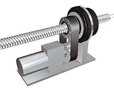
Applications that require long stroke lengths and/or large screw diameters can result in very high screw inertia, which may require a larger motor and make it more difficult to precisely control the load. One advantage of a rotating nut ball screw assembly — also referred to as a driven nut — is that it has relatively low inertia, since the screw shaft remains stationary and only the nut rotates.
Driving the ball nut (rather than the screw shaft) can significantly reduce the inertia of a ball screw driven system. Image credit: SKF Group
Screw assemblies that use rollers as the load-carrying element come in several varieties, with the most common being the traditional planetary roller screw, which provides high load capacities and very high rigidity, capable of outperforming ball screw and hydraulic actuators in some heavy-duty applications. But another type of roller screw — the recirculating roller screw — offers high load capacity and rigidity, but with very fine leads for applications that require positioning with high resolution.
Recall that planetary roller screws use a screw, nut, and cylindrical rollers that all have matching threads. The rollers also mesh with geared rings at the ends of the nut, allowing them to spin on their own axes while they revolve around the screw, so that each revolution of the screw shaft advances the nut by a distance equal to the lead of the thread. With many more contact points than ball screws, the primary benefits of the roller screw design are higher load capacity and better rigidity.
Planetary roller screws use a screw, nut, and rollers with matching leads. The ends of the rollers engage with geared rings on each end of the nut, allowing the rollers to spin on their axes while revolving around the screw shaft. Image credit: Tolomatic
Recirculating roller screws also use a threaded screw and nut, but the rollers are grooved rather than threaded. In other words, each roller has a series of individual grooves which lie perpendicular to the roller’s axis. This means that as the rollers revolve around the screw shaft, they’re displaced axially within the nut, along the length of the screw, by a distance equal to the lead of the screw and nut thread.
Recirculating roller screws use a screw and nut with matching leads, but the rollers are grooved, so they advance axially within the nut as they revolve around the screw. Image credit: Ewellix
The behavior of the rollers within the nut is a key difference between planetary and recirculating roller screw designs. In the traditional planetary design, the threaded rollers simply advance along the screw shaft and do not move axially within the nut. In the recirculating design, the rollers only have grooves — not threads — so they do move axially within the nut, and therefore, need to be recirculated.
The most common recirculating roller screw designs use a cage with slots that are slightly longer than the roller length, allowing the rollers to rotate and to move axially within the nut. After a roller makes one revolution around the screw, cams at each end of the nut disengage the roller from the screw shaft and shift the roller into a groove in the nut body, returning the roller to its initial position within the cage, but advanced axially on the screw by an amount equal to the screw lead.
This video from Rollvis shows the operation of a typical recirculating roller screw design, using a cage that holds the rollers and allows them to move axially within the nut.
Another recirculating roller screw design forgoes the use of a cage. In the cage-free design, when the rollers complete one revolution around the screw, they disengage from contact with the screw, but not with the nut. Cam rings on each end of the rollers guide the rollers into the nut’s axial groove, which is threaded, and ensure consistent pressure between the rollers and the nut.
The primary benefit of recirculating roller screws is the availability of very fine leads. Most manufacturers offer recirculating roller screws with leads as small as 1 mm, and some even offer fractional-millimeter leads. These small leads provide high resolution while also requiring lower input torque for transmitting loads. In contrast to traditional planetary roller screws —which are typically used in applications that require very high thrust forces and rigidity, such as pressing operations — recirculating versions are ideal for applications that require very fine, high-precision motion, such grinding equipment and optics alignment.
From a mechanical standpoint, one of the more challenging applications in linear motion has traditionally been to move two or more loads independently, as is required in some handling, transport, and inspection applications. While using multiple linear systems, or preassembled actuators, is a simple solution mechanically, this option typically requires a significant amount of space and cost. But there are several types of linear systems that allow users to mount more than one load and move each one independently.
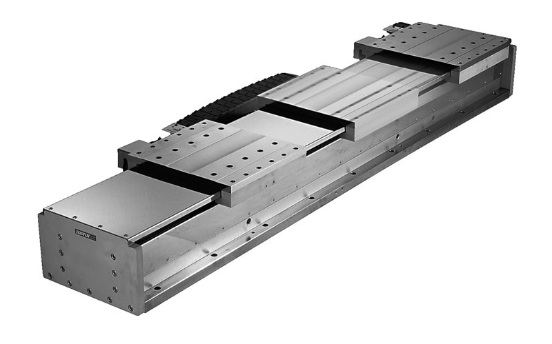
One of the most common linear motion systems for moving multiple loads independently is the linear motor. Most linear motor designs — whether iron core or ironless — use forcers that contain windings and are powered directly, so multiple forcers can be installed on the magnet track and controlled with different move profiles and strokes. Linear motors with multiple forcers, or carriages, are often used for highly dynamic moves that require very precise control over velocity or position. In fact, many linear-motor-based conveyor systems are based on the concept of a linear motor with multiple forcers.
Since each forcer (carriage) is powered directly, linear motors are well-suited for applications where multiple loads need to be moved independently. Image credit: Hiwin
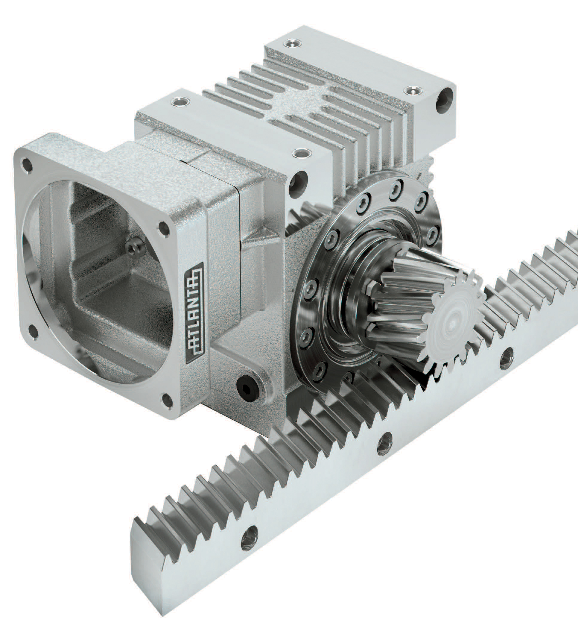
Another traditional linear motion system that allows multiple loads to move independently, is the rack and pinion drive. Because the motor and gearbox are mounted directly to the pinion, it’s relatively simple to mount additional motor-pinion combinations on a single rack, with each programmed for a specific travel and move profile. Rack and pinion systems with multiple, independent carriages are ideal for large gantry and transport applications and are often used in robot transfer units.
With the pinion driven directly by a motor-gearbox combination, it’s easy to assemble multiple pinions, each driven independently, to a single rack. Image credit: Atlanta Drive SystemsIn the dual-belt design, one belt is stationary and the other belt rides around a driven pinion with idler rollers on each side. Image credit: Bell-Everman
A less traditional solution for moving multiple loads independently is to use a belt drive actuator — but not with the typical belt-and-pulley arrangement that many of us are familiar with. This type of linear actuator uses two belts that are configured in a specific way, similar to a rack and pinion drive.
One belt is static and mechanically fixed to a base, such as an extrusion — analogous to the rack in a rack and pinion drive. The other belt is a short, continuous loop that snakes over a motor-driven pinion and through idler rollers on each side of the pinion. The load is attached to a carriage, which contains this moving motor-pinion combination. Like the rack and pinion system, the dual-belt actuator design makes it simple to add more carriages — each with its own motor-pinion assembly — and control them independently. The dual-belt design also puts tension on the belt where it comes into contact with the pinion, which eliminates backlash and minimizes belt stretch.
This video from Bell-Everman shows their dual-belt actuator design, which allows multiple carriages to move independently on a single actuator.
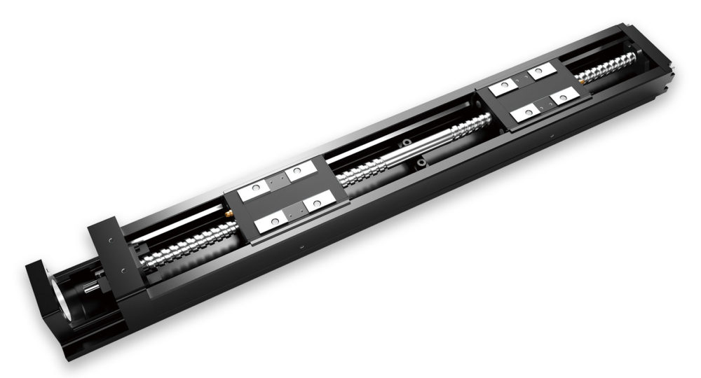
There also exist actuator designs that use two ball or lead screws — one with a left-hand thread and one with a right-hand tread — that are pinned or welded together. Each screw has a nut and carriage, and one motor drives the entire assembly. This setup allows the carriages to move simultaneously, but in opposite directions — moving either toward or away from each other with the same move profile. This is a less flexible arrangement than the linear motor, rack and pinion, or dual-belt designs described above, but it can be useful in applications that require a clamping-type motion with precise force and speed control.
Some screw-driven actuators incorporate both left- and right-handed screws, welded or mechanically joined and driven by a single motor. Each screw has a nut, so the loads move towards or away from each other with the same move profile. Image credit: THK
For applications that involve corrosive environments, designers of linear motion systems can take precautions such as using covers to protect vulnerable components, ordering parts with special coatings or platings, and strategically placing sensitive components within the machine or system to minimize their exposure to hazardous liquids or fumes.
But some applications — due to the nature of the contamination or to comply with industry regulations — require the use of stainless steel materials wherever possible. However, there are many steel alloys that make up what we generally refer to as “stainless steels,” and manufacturers offer linear motion components and sub-components in a variety of different stainless steel grades.
Manufacturers offer several options or corrosion-resistant linear motion systems. Image credit: THK
To help you navigate the range of corrosion-resistant linear motion products, here’s a primer on the most common stainless steel options, along with examples of where each one is typically used in linear motion systems.
There are four main families of stainless steels, characterized by their crystalline structure, or arrangement of atoms: austenitic, ferritic, duplex (mixed austenitic-ferritic), and martensitic. Most stainless steels used in linear bearing applications are in the austenitic and martensitic families. Austenitic stainless steels are chromium-nickel alloys which can have other elements — such as molybdenum, manganese, and nitrogen — added. Martensitic stainless steels are also chromium alloys, but with less chromium and more carbon than austenitic types. This makes martensitic stainless steels harder — but less corrosion-resistant — than austenitic types.
Several standardization bodies — such as JIS (Japanese standard), DIN (German standard), and BS (British standard) — have their own systems for grading stainless steels, but the most commonly used are the SAE/AISI (Society of Automotive Engineers/American Iron and Steel Institute) and the EN (European standards) systems.
The SAE/AISI system uses 3 digits to specify individual grades of stainless steel (316 or 440, for example), with 300 grades being in the austenitic family and 400 grades being in the martensitic family. The EN system uses a “1” followed by four decimal places (1.4112, for example) to designate different grades of stainless.
The most popular types of stainless steels are in the austenitic family, particularly 316 and 304 grades. The most significant difference between 316 and 304 stainless steel is that 316 contains molybdenum, which gives it very high corrosion resistance — particularly for environments with chlorine or saline. In fact, 316 stainless is sometimes referred to as “marine-grade stainless.” There is also a 316L (“L” = “light”) grade of stainless, which has a lower carbon content than 316, making it more corrosion-resistant.
Although 304 stainless is the most commonly used austenitic grade, 316 and 316L grades are typically preferred for applications such as food processing, semiconductor, and pharmaceutical manufacturing. In linear motion systems, 300-series stainless materials are typically used for recirculation components, lube fittings, and other non-load-bearing parts.
The “basic” grade of austenitic stainless steel is 304, and from there, the addition of various elements creates other grades with properties that make them suitable for specific applications, such as machinability or corrosion-resistance. Image credit: jmcampbell.com
Because they’re harder than austenitic types and can better handle extreme pressure and Hertzian stresses, martensitic stainless steels, such as 440 grades, are often used for load-bearing components such as balls, shafts, and guide rails. Other critical components, such as bearing housings, are also commonly made from martensitic stainless steels.
Another form of martensitic stainless steel — precipitation hardening martensitic, such as grade 630 — is sometimes used for ball screw shafts, because it has high strength and hardness after heat treating, with corrosion-resistance similar to 304 stainless.
440 grades of martensitic stainless steel are often used for load-bearing elements such as balls and guide rails because they have added carbon to improve hardness. Image credit: jmcampbell.com
Each manufacturer has different offerings in terms of the grade of stainless steel used for each component of the linear motion system. For example, some manufacturers use grade 440C stainless steel for balls, while others use grade 440B or grade 431. So it’s important to ensure that the grade of stainless steel used is appropriate for the chemical or type of contamination that it will be exposed to in the application.
The grade of stainless steel used will also affect the static and dynamic load capacities of the system, so be sure to use the appropriate (reduced) load capacities when performing load and life calculations.
Several types of non-recirculating linear bearings use a cage to contain the rolling elements, maintain consistent spacing between them, and ensure even load distribution. But in each of these non-recirculating designs, the cage “floats” between the two moving components, meaning that it’s not constrained and can gradually move away from its intended, centered position. This movement of the cage is referred to as cage creep.
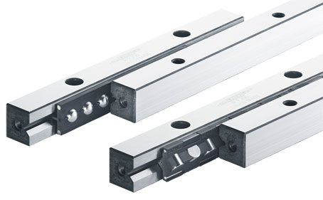
Although not necessary, cages are often used in non-recirculating ball and roller slides to prevent ball-to-ball or roller-to-roller contact. Image credit: Schneeberger
Although a cage isn’t necessary for the proper operation of a crossed roller slide, many designs use cages to prevent contact between the rolling elements, which in turn, reduces noise and friction.
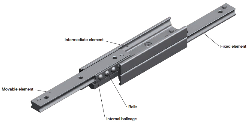
In telescoping slides, the cage not only contains the rolling elements and ensures even load distribution, it also determines the slide’s load capacity for applications with shorter strokes — particularly in partial extension designs. (For longer-stroke applications — typically achieved with full extension or over-extension designs — the rigidity of the intermediate element determines the slide’s load capacity.)
Cages are also used in both recirculating and non-recirculating types of needle roller bearing linear guides, to contain the rollers and ensure their proper movement during the stroke.
Unlike their regular ball spline counterparts, the balls in a stroke ball spline don’t recirculate, and so require a cage (also referred to as a ball retainer) to hold the balls.
Telescoping slides use a cage to contain the balls and ensure even spacing. Image credit: Rollon
In ideal applications, the cage will remain in its intended, centered position. But if the full stroke of the bearing isn’t used, or if there are shock or vibration loads, the cage can move, or creep, to one end of the bearing assembly. Vertical applications can also induce cage creep, simply due to the force of gravity.
When the cage becomes misaligned from its center position, it can shorten the stroke of the bearing, and if end stops are provided at the ends of the rails, the cage can bump into the end stop when a full stroke is attempted. Although this forces the cage back to its centered position, it causes both the cage and the balls (or rollers) to slide, rather than roll, which increases friction and heat. The force of the cage hitting an end stop can also damage the cage or one of the guide elements.
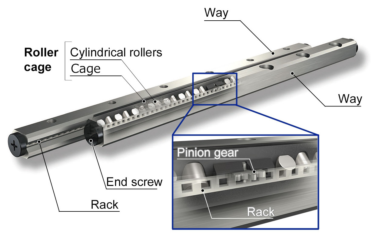
One method to prevent cage creep uses a rack and pinion type system, with the pinion integrated into the cage and the rack integrated into one of the guides. Image credit: IKO Nippon Thompson
Manufacturers have developed several methods to combat cage creep. One popular method is to use a rack and pinion type assembly, with the pinion gear integrated into the cage and the rack integrated into one of the guide rails. Another method is to use a studded center roller that meshes with indentations machined into one of the rails.
Another anti-creep device uses a studded center roller that engages with indentations in the rail to keep the cage properly centered. Image credit: Nippon Bearing
A few types of linear guides don’t require or don’t use anti-creep mechanisms. For example, recirculating linear bearings that use cages — such as the needle roller types described above — don’t experience cage creep, since the cage is an endless component that runs completely around the recirculation path. And although stroke ball splines do experience cage creep, their design and compact size precludes the use of anti-creep mechanisms, so it’s important to incorporate occasional full-length strokes to re-center the cage – especially if the application involves high travel speeds or vertical installations.
Air bearings provide several advantages over rolling element bearings, including higher travel accuracy and reduced friction and heat generation. But because air is compressible, air bearings can be less stiff and exhibit more deflection under load than similar rolling element bearings (although the stiffness characteristics of air bearings are very linear). However, the compressible nature of air can be used to create a preloaded air bearing, which increases its stiffness.
Just as preload in a rolling element bearing is a load induced between a rolling element and its raceway, preload in an air bearing is a load induced between the bearing and its guide surface. There are four common methods for inducing preload on an air bearing: by adding mass to the bearing, by applying a magnetic force, by applying vacuum, or by mounting two air bearings facing each other on opposite sides of a guide surface.
Image credit: G. Khim, C-H Park
Regardless of the preloading method, as the load is applied to the air bearing (whether via added mass, opposing forces, magnetic force, or vacuum), the air film that supports the bearing compresses, the air gap gets smaller, the pressure in the air film increases, and the air film becomes stiffer.
As the preload on an air bearing increases, so does stiffness. Image credit: Roger Cortesi, MIT
Each preloading method has advantages and drawbacks, but for applications where added mass would significantly compromise acceleration and settling times, where space constraints make it difficult to mount two air bearings in an opposing orientation, or where adding magnetic material to the surfaces would be too costly, vacuum preloading offers a relatively simple solution that doesn’t add mass or require special assembly and mounting considerations.
Image credit: PI Nelson Air
Although it might seem that air pressure and vacuum would work against each other, the level of vacuum used for a preloaded air bearing is relatively low compared to the bearing pressure, so the bearing is still lifted from the guide surface by the applied air pressure.
To achieve preload, vacuum is applied to a portion of the bearing surface — typically the center portion. This means that the bearing pressure is applied around the perimeter, creating a seal to contain the vacuum area and prevent the vacuum from drawing in any contamination from the environment. A groove between the vacuum area and the bearing area is connected to ambient pressure and prevents flow between the exiting bearing air and the vacuum. The preload force is equal to the size of the vacuum area multiplied by the differential between the bearing pressure and the amount of vacuum.
Vacuum preloaded air bearings are often used in planar stages. Image credit: PI
The pressure at the area where vacuum is applied is independent of the bearing flying height (the distance above the mounting surface), so preload remains constant even if the flying height changes. For example, if the flying height increases, the pressure in the bearing area decreases, so that the bearing experiences a higher pulling force (preload). This interplay between the air pressure and vacuum ensures an equilibrium between the preload force and the pressure for a given flying height.
Not only do vacuum preloaded air bearings have high stiffness, by adjusting the differential between the bearing pressure and the vacuum, the thickness of the air film — and in turn, the flying height — can be adjusted, making vacuum preloaded versions ideal for applications that involve ultra-fine, precise vertical positioning, such as lens focusing.
Hardness is a common specification for linear shafts and guides — especially those used with ball and roller bearings, where the guide encounters extremely high loads over very small areas. The hardness of a bearing surface can significantly affect the life of the system and is often accounted for by applying a hardness correction factor when calculating bearing life.
Unlike other mechanical properties, such as yield strength, hardness isn’t defined by a material’s stress-strain diagram. In fact, some experts argue that hardness isn’t a fundamental property of a material, and should only be considered in conjunction with other material properties, such as tensile strength, proportional limit, and ductility.
There are three types of hardness for materials: scratch hardness, which describes plastic deformation or fracture due to friction; indentation hardness, which describes resistance to localized plastic deformation due to a constant compression load; and rebound hardness, which is related to the material’s elasticity and describes the height of the “bounce” of a diamond-tipped hammer dropped onto the material from a specified height.
For rolling element linear bearings, we’re typically concerned with indentation hardness due to the extreme forces caused by point or line contact of the load-carrying balls or rollers.
There are several methods for testing and defining the indentation hardness of a material, but the most common methods used in linear bearing applications are the Brinell and Rockwell tests. Both methods determine hardness by the depth of penetration of an indenter (typically a hardened steel ball or a diamond cone with a spherical end), which is forced with a predefined load into the surface of a specimen for a specific period of time. Hardness is then determined based on the dimensions of the indentation.
Brinell hardness is found by dividing the load by the surface area of the indentation (as measured with a microscope and a superimposed scale).
The Brinell test uses the area of the indentation to determine hardness. Image credit: Tec-science.com
HB = Brinell hardness (kg/mm2)
P = applied load (kg)
D = diameter of indenter, or ball (mm)
d = mean diameter of indentation (mm)
For heat-treated plain carbon steels and mild steel alloys, the tensile strength (in psi) is roughly equal to 500 times the Brinell hardness.
Rockwell hardness is determined by first using a minor load to force the indenter into the material and then, after equilibrium is reached, applying a major load. When equilibrium is reached with the major load, the major load is removed while the minor load is still applied. This allows the material to partially recover, and the permanent depth of penetration is used to calculate the Rockwell hardness.
The Rockwell test takes into account the differential indentation depth between the minor load and the major load.
HR = Rockwell hardness
E = constant, depending on the type of indenter (130 for Rockwell scale B and 100 for Rockwell scale C)
h = permanent depth of penetration due to major load (mm)
The equation for Rockwell hardness is sometimes written as:
e = permanent depth of penetration due to major load, measured in units of 0.002 mm (e = h/0.002)
Rockwell hardness is measured according to different scales, depending on the type of material being tested. Each scale specifies the type of indenter and testing load to be used, along with typical materials to which that scale is applied. The most common Rockwell scales used for bearing materials are B (HRB) and C (HRC).
There are ways to increase the hardness of a metal, with induction hardening and case hardening often used for linear bearing components. Induction hardening increases the hardness of the material’s surface to a depth ranging from 0.5 mm to 10 mm, while case hardening increases the hardness of the surface to a depth ranging from 0.25 mm to approximately 6 mm.
Here we offer some tips for converting a fluid-power-driven axis to electrical actuation.
By Ryan Klemetson • Business Development Manager | Tolomatic, Inc.
As explained in Part 1 of this article series on motioncontroltips.com, hydraulic systems offer long service life, but they’re not as efficient as electric systems. Electric systems also provide precise position, velocity, and speed control with more efficient operation. They operate in a closed loop environment for easy data collection, and they are virtually maintenance free.
In fact, as electric rod-style actuators become capable of delivering forces comparable to those of high-end hydraulics, they’ll become increasingly viable replacements for hydraulic systems in many applications. Evaluating capabilities and limitations and aligning them with system goals and objectives will help determine the best choice for the application.
When switching to electric — know the required force
When considering a switch to electric actuators, first determine the application’s required working force. To estimate this force value, the typical approach is to adjust the hydraulic work port or system pressure until the operation can no longer be performed. Electric actuator systems rely on current through the servomotor to produce torque to the mechanical system, which drives the screw to turn and generate force. This is a huge advantage; force is instantaneous. In hydraulic systems, where system rigidity isn’t optimized, the hydraulic actuator must wait for pressure to build until force is achieved.
Another big advantage of electric systems is that the servo controller automatically regulates current — and so the electric actuator system essentially uses current on demand. Any adjustment happens automatically. In contrast, a hydraulic power unit must always maintain system pressure for the hydraulic cylinder to actuate, which can significantly degrade their overall system efficiencies.
When selecting an electric actuator system, it’s essential to consider the motor’s RPM and torque capabilities, coupled with the screw lead in the electric actuator. Matching speed and torque from the servomotor with the leadscrew’s mechanical output can be complex. getting the extreme forces that hydraulics can produce is entirely possible with electric technology, but typically, the electric actuator deployed will have a larger body diameter and the electric actuator system will have a velocity maximum that can’t be exceeded. The complexity in sizing a system can easily be overcome as actuator and servo component manufacturers provide easy-to-use motion control sizing software packages that factor in all these variables.
In fact, converting from a hydraulic to electric system requires understanding three key variables: force, motion profile and electric actuator technology. Adding actual force and motion data into a manufacturer’s sizing software will yield an accurate recommendation for conversion.
Don’t oversize the actuator: The first step in the conversion process is to understand the amount of work being done. This work (force) is a function of the hydraulic pressure in the cylinder. However, getting an accurate measurement of the force being applied by hydraulics can be complex. The most common conclusion is to use the maximum-rated pressure of the hydraulic system. This assumes that prior engineering work didn’t significantly oversize the hydraulic system.
Essential to converting from hydraulic to electric is to avoid oversizing.
Oversizing a hydraulic cylinder is common due to the relatively small effects it can have on the overall system cost. The issue is that that same cannot be said of electric actuators. The price of an electric actuator is significantly affected by upsizing — so excess safety margin must be avoided. In fact, the biggest mistake is to oversimplify the force calculation process.
Know the real peak force: To avoid costly sizing mistakes, determine the real peak force of the hydraulic cylinder to be replaced. Also remember that oftentimes, hydraulic cylinders are intentionally oversized.
To be clear — sizing an electric actuator to replace a hydraulic cylinder isn’t as simple as calculating the old system’s capabilities. Such approaches often employ a basic system-pressure formula, so called because the calculations assume the application of maximum system pressure to the cylinder’s full piston area. Using this system-pressure value in for force calculations isn’t recommended.
Instead, it’s best to determine the hydraulic cylinder’s true peak and continuous working force. One approach is to record values of the application while in operation, though this can be challenging … especially on an existing machine. If it’s in fact possible to record these values, exact pressure readings aren’t necessary … as even an estimation to within 15% of the actual force is a useful range. Another way to determine application forces is to use a load cell or install an electric actuator on the machine axis in question. Of course, these solutions can also prove difficult if not impossible to implement in existing machines.
Hydraulic system output force is equal to the area of the piston’s working surface multiplied by the rated system pressure. However, using system pressure in force calculations (to choose an electric actuator replacement) can often result in an oversized and overpriced electric solution.
The next best and often most practical way to determine required force is to measure hydraulic pressures in the fluid-power system while the process is in operation. In fact, there are three different locations in a hydraulic system at which to take pressure measurements. The closer one can get to the actual point of work, the more accurate the measurement. Conservative measurements yield useful results — so that the replacement actuators (and their motors) aren’t undersized or significantly oversized.
Measuring hydraulic pressures at the actual hydraulic cylinder (more specifically, on each side of the cylinder) yields the most accurate estimations of required force. The area of rod side of piston equals the bore area minus the rod area. That yields an application force equal to the difference in force between the two sides: Force = (Area1 · πr2 x P1) — (Area1 · πr2 x P2).
This is the most accurate method for conversion.
Other tips for assessing an axis’ required force: Take a video of the process in motion to learn how much time is needed to make the target travel distance. This is useful for sizing the mechanical assembly and support finalizing motor and drive selection. Also take videos of any pressure gauges used in measuring pressures. This allows investigation of pressure across the entire stroke to better identify if there are pressure spikes requiring consideration.
In addition, be sure to identify special requirements — including the need for constant velocity or the maximum time to complete a given move, for example. Here, an application sizing worksheet can be a useful tool to document these requirements and provide a quick snapshot of what’s necessary for a specific application.
Finally, measure the fluid-power system working pressure and the return pressure. Every hydraulic system is different. Usually, there’s minimal backpressure in return lines … though some systems can have high return pressure between the cylinder and the valve. In these instances, this pressure does influence the hydraulic cylinder’s output force.
The most accurate force calculations determine the dynamics on both the blind (piston) end and the rod end of a hydraulic cylinder.
Force is generated whenever pressure is applied to a surface area. Therefore, any back pressure applied to the rod end of a hydraulic cylinder during an extend move will offset some of the force applied by the primary working pressure on the cylinder’s blind end. The most accurate calculations — which we call the dual-force method — account for this effect of back-pressure offset and the resultant force.
Example: Why proper measurements are a must for correctly sizing actuators
Shown here is one example illustrating how a relatively high back pressure can affect primary working pressure in a fluid-power-driven system.
Assume that for a given hydraulic system, the pressure rating is 103 bar. If we use this value alone in area x pressure calculations to calculate force for a given cylinder size, we’ll end up with an electric-actuator solution that’s vastly oversized. In fact, our example application only uses 2,366 N of thrust … so the use of system pressure would’ve resulted in an actuator five times larger than required.
This example uses very small forces compared to what typical hydraulic systems can produce, but it highlights the importance of identifying and using accurate application data.
Oversizing an electric actuator — by using double or triple the needed force capacity — can add thousands of dollars of unnecessary cost to the system.
When sizing hydraulic cylinders, it may only cost a few hundred dollars to oversize by selecting a larger bore size for more force. However, oversizing an electric actuator — by using double or triple the needed force capacity — can add thousands of dollars of unnecessary cost to the system. That’s why proper measurements are critical to right-sizing electric actuator systems.
With larger hydraulic-cylinder bores and higher oil pressures come increased output force capabilities.
The danger of fluid-power sizing
Because fluctuations in fluid pressure are common and the cost of fluid-powered cylinders is low, it’s typical that hydraulic cylinders are sized two or threefold larger than that needed by the application. Engineers can consider this oversizing to be a design safety margin or kind of insurance. However, the practice of oversizing can obscure an application’s actual force requirements — making them appear quite high when in fact they are significantly lower than the cylinder’s maximum rating.
As a hydraulic cylinder gets bigger, its force capabilities grow because force = pressure × area. As the bore and oil pressure of a cylinder increase, the output force capability grows rapidly. The force output of an over-sized cylinder is much higher than what the application specifies.
Using inflated force values when quantifying a hydraulic cylinder’s real-world function creates two challenges for conversion to electric actuation.
Without thorough investigation, it may make the application’s force requirement seem much higher than what an electric linear actuator can deliver. It may (mistakenly) look impossible to convert the application to electric.
Electric actuators can have a higher purchase price than hydraulic cylinders. Unnecessary oversizing can lead render electric actuators unaffordable.
All article images from Tolomatic Inc. | tolomatic.com
Linear stage designs can range from long-stroke, high-load gantries to micropositioning and nanopositioning stages with light payloads. Although all linear stages are designed and constructed to provide high positioning accuracy and repeatability and to minimize angular and planar errors, stages for micropositioning and nanopositioning applications require additional considerations in component selection and design to achieve these very small, precise motions.
Micropositioning refers to applications where movements are as small as one micron, or micrometer. (One micron is on millionth of a meter, or 1.0 x 10⁻⁶ m.)
Nanopositioning refers to applications where movements are as small as one nanometer. (One nanometer is one billionth of a meter, or 1 x 10⁻⁹ m.)
To achieve positioning in the micron or nanometer range, one of the key design principles is to eliminate as much friction as possible. This is why nanopositioning stages exclusively use non-contact drive and guiding technologies. For example, the driving force for a nanopositioner is typically provided by a linear motor, piezo actuator, or voice coil motor. On the other hand, micropositioning can often be achieved with more traditional mechanical drivetrains such as ball and lead screws, although linear motors are also sometimes used for micropositioning applications.
This nanopositioning stage uses noncontact components – a voice coil motor drive and air bearing guide – to eliminate friction. Image credit: PI
Friction-free guide technologies used for nanopositioning include air bearings, magnetic guides, and flexures. Because these technologies don’t involve rolling or sliding contact, they also avoid the backlash and compliance that degrade positioning accuracy in traditional mechanical transmissions. For micropositioning stages, non-recirculating linear guides are typically the best choice, since they don’t experience pulsations and varying friction levels from balls entering and exiting the load zone. However, some high-accuracy recirculating linear guides have been optimized to reduce these pulsations and friction variations, making them suitable for micropositioning applications — particularly those with longer total stroke lengths.
Closed-loop operation using feedback from a capacitive sensor compensates for effects such as hysteresis and creep in this piezo flexure stage. Image credit: Aerotech
In addition to friction and backlash, other effects, such as hysteresis and creep, can interfere with the system’s ability to position at the micron or nanometer level. To deal with these effects, micropositioning and nanopositioning stages are typically operated in a closed-loop system using a position feedback device that has a much higher resolution than the required positioning accuracy. This often means single-micron (or better) resolution for micropositioning applications and single-nanometer resolution for nanopositioning requirements.
Technologies that can provide these extremely high resolutions include glass scale optical encoders, capacitive sensors, and interferometer-based encoders. However, because nanopositioning stages are typically very small devices, capacitive encoders — which can be constructed in a very small footprint — are typically the best option. For micropositioning stages, high-resolution magnetic encoders are sometimes used as well — particularly when the environment involves fluctuating temperatures or high humidity.
Despite their special design and construction, micropositioning and nanopositioning stages are relatively easy to customize — especially in terms of materials, finishes, and special preparations — and apply in unique applications. Case in point: Stages that are constructed with friction-free components are typically suitable for cleanroom and vacuum applications, since they don’t create particulate matter due to rolling or sliding friction and don’t require lubrication. And if a non-magnetic version is required, standard steel components can be easily replaced with non-magnetic alternatives without concerns regarding reduced load capacity. In many applications where micropositioning and nanopositioning stages are used, the machine design includes features such as damping mechanisms that can counteract even the slightest vibrations and advanced control algorithms to compensate for disturbances.
Linear motion components include everything from various types of linear actuators to linear guides, slides and ways, and a host of components in between. One thing they all have in common is that their development and production are influenced by both technological trends as well as broader market forces. One of those forces is has been the coronavirus pandemic. The pandemic has impacted every aspect of life, including many segments of manufacturing.
Laboratory automation applications have seen an uptick as a result of the coronavirus pandemic. Companies like Festo have worked to develop intelligent, tested subsystems for the automation of liquid media and sample handling applications.
Not surprisingly, one area that has seen growth during the pandemic is laboratory automation. As Darren O’Driscoll, Product Market Manager for Pneumatic Motion Products at Festo explains, “for the past two years, Festo has been working with laboratory equipment OEMs in the fight against COVID. We’ve been developing precision sample handling and vial capping/decapping solutions based on multi-axis motion systems. We’ve also devoted significant resources to the development of precision liquid handling systems.”
Precision liquid handling in automated laboratory devices involves rapid, precise aspiration and dispensing of fluids into and out of vials and microwell plates. New products developed by Festo include open- and closed-loop pipettes and pipette heads, new valves and valve controllers, and compact all-in-one compressed air and vacuum generators for onboard air. The partnership between the automation supplier and OEM allows the equipment manufacturer to focus on the science of the test or assay while the automation supplier innovates the motion of handling and liquid dispensing.
Another company seeing increased activity in laboratory automation is igus. Matt Mowry, igus drylin Product Manager, says that “this is one of our major industries, with customers always looking for low-cost, lightweight and self-lubricating bearing systems in these environments.”
Aside from laboratory automation, other growth areas in automation include battery production as well as food and beverage manufacturing. As Festo’s O’Driscoll explains, “automation in battery production drives down cost through higher productivity and is in response to the transition to electric vehicles. Food and beverage automation is driven by a desire to lower worker density on the processing and packaging floor for a safer environment and to compensate for labor shortages. Food handling is stimulating development of new gripping solutions both in soft grippers and adaptable grippers. Research continues on the application of agricultural automation in terms of self-guided mobile robotic picking systems for delicate fruits and vegetables.”
Though the exception, there exist crossed-roller slides (as well as contained carriages that mate to essentially standard guideways) with recirculating roller circuits. Though less common than the traditional (non-recirculating) crossed-roller types, these recirculating slides excel in applications that must bear high loads and benefit from the rigidity of crossed-roller arrangements. (Image courtesy NB Corp.)
Also, as automation technology has become more affordable and increasingly easy to use, smaller manufacturers have embraced automation as a response to the pandemic, especially given labor shortages.
The pandemic has also caused many supply chain issues. In fact, the prospect for further supply chain disruptions into 2022 is all but given. As Festo’s O’Driscoll remarks, “supply issues top nearly everyone’s list of concerns. You can deal with pricing fluctuations. If you do not receive product, you’re in deep trouble.” As a result, people are becoming more resourceful and are doing their best to cope with the uncertainty. O’Driscoll continues: “Many end users and suppliers build up inventories of crucial components. Companies focus on their approved components books by identifying slides, actuators, and other components that are readily available. Their suppliers must demonstrate to these companies that they have the ability to maintain supply. Years ago, Festo identified the 20% percent of its product catalog that satisfies 80% of application needs and created the Stars of Automation core products initiative. Starred core products are globally forward deployed and always in stock. This has been a lifeline for many customers during the current disruption.”
On the flip side, a key trend that has emerged from the pandemic is the automation of design and ordering through free online tools. Many companies offer these online tools as a way to engage customers and expand their reach. Companies like Festo recognize that with such online tools available, the faster a company can design and place an order for a gantry system, for example, the quicker it can place into the order queue. The same goes for transparent online ordering that provides near instantaneous answers to questions such as: Is the component in stock? When will it ship? What does it cost? When can I receive technical drawings?
Overall, some familiar trends continue for linear motion components such as linear guides, slides, and ways. For instance, it’s still the case that designers want more compact components in order to build smaller machines. Shrinking the size of guides and slides increases component density, while expanding machine production capability. Even though components are smaller, guide and slide performance have to be equal to or better as compared to larger units.
Festo’s O’Driscoll adds that Festo “has introduced a compact slide for precision handling, press fitting, pick and place, and light assembly applications. This slide and yoke plate were machined from a single piece of aluminum, which ensured stiffness and accurate alignment. Backlash free piston rod/yoke connection contributed to the slide’s precision and extended service life.”
Matt Mowry from igus sees a related trend towards lighter components in linear motion applications. “The trends are towards light-weight components, especially those that do not require maintenance,” says Mowry. “Also, customers are asking for linear components that are quieter, especially if they are being used in commercial or laboratory environments.” Darren O’Driscoll from Festo agrees. “The trend to small, lighter in weight components has caused other shifts in materials. For example, air preparation units have traditionally been constructed of cast aluminum. Today, there is a transition to high strength polymers.”
Some of the surest, time-tested methods of linear actuation are screw drives. Whether lead- or ball- or roller screws, screw actuation remains a large part of the linear actuation equation, thanks to their reliability, accuracy, and relative simplicity of operation.
Recently screw drive developments have included advances in materials as well as manufacturing methods leading to enhanced performance in terms of greater load densities and higher load capacities. This, coupled with more integrated design offerings has meant that screw drives are finding their way into newer applications in a diverse array of settings. Screw manufacturers are seeing marked upticks in business in certain industries such as robotics and 3D printing among others, as some of the top screw manufacturers told us.
An uptick in automation applications has meant an increased demand for screw drives, such as these metric-sized ball screws from Thomson.
As far as screw technology goes, there is an ongoing shift in preferences regarding ball-screw standards. “The traditional ‘Saginaw’ style ball screws that we are all familiar with are still popular in the U.S., but the trend over the past several years has been toward the ISO standard metric ball nut body styles,” notes Ron Giovannone, Director for Application Engineering & Sales Support with Nook Industries. “I expect this trend to continue over the coming decade,” adds Giovannone.
When it comes to applications for screws, manufacturers have seen increased activity in some industries. For instance, Jeremy Gong, Area Sales Director for Thomson Industries, Inc., says that throughout 2021 Thomson saw increased interest and demand “predominantly driven by shortages and lengthening lead times across the board. This was a mix of customers trying to meet existing demand as well as the pursuit of safety stock at all levels.” As for industries and applications that saw growth, Gong adds that “there has been increased interest in automation, likely driven by shortages in labor throughout the U.S. Specifically, factory automation has played a large part in our precision ball screw products. The medical space also saw increased interest in our miniature guide offerings as well as our stepper motor linear actuators to be used in desktop analysis applications.”
Its’ no secret that the coronavirus pandemic has had an impact on virtually every industry in some way. Perhaps most notably are supply chain issues across the industrial sector.
“In the initial stages of these challenging market dynamics, end users and integrators adapted by placing a heavier burden on their own inventories,” notes Saurabh Khetan, Product Line Manager for Lead Screws with Thomson Industries. “This was coupled with attempts to stay ahead of shortages by placing POs with higher-than-normal volumes to ‘get it into the system’ or POs with releases far into the future. They did so in an attempt to stave off negatively impacting their own customers” adds Khetan.
A medical application using stepper motor linear actuators from Thomson.
However, Khetan notes that as supply chain disruptions persisted, “there has been increased acceptance by end users and integrators as well as their own customers of these challenges being here to stay for at least the foreseeable future. We have also seen evidence of end users shopping around to other suppliers and delaying new generation launches of existing programs.”
Screw protection for robotic 3D printers
Some applications can not only call for new screw designs but also redesigns of support structures and other ancillary screw components such as bellows covers and cable carriers. For instance, take robotic 3D printing systems.
The motion and protection company Dynatect has seen a surge in demand for dynamic protection components used on 3D printers large enough to create full-scale cars or even homes. There are many new manufacturers in this space, with mechanical structures at unprecedented scale. Specifically in printing homes, these large-scale printers are referred to as “factory in the field”, given their portability from location to location. Beyond printing in concrete these “factories in the field” include cutting out of windows and doors, painting, and scanning for quality verification. To accomplish this, large-scale 3D printers merge the best features of printing, robotics, and machine tooling – combined with being used outdoors like construction equipment.
These robotic 3D printing systems often use large (2 ft x 15 ft) spiral-column lifting mechanism to change the height of the printing assembly. These lifting columns have multiple bands of intertwining stainless steel threads which are exposed to process generated debris like cement grit, window cutting dust, and paint splatter. Protecting these precision lifting columns is critical for repeated performance and typically are covered by bellows. With ten different bellows manufacturing capabilities from sewn to dip-molded to vulcanized, Dynatect can offer the best bellows construction method to optimize retracted/expanded ratio for full motion, durability, and price. This construction is matched with MIL-SPEC materials specifically for harsh outdoor environments including UV exposure, outdoor weather, and process generated debris.
Bellows protecting sensitive machine components and cable carriers for protecting cables and hoses (shown circled in yellow) from Dynatect are used in this large 3D robotic printer.
Robotic 3D printing systems are fed by a collection of moving power and control conductors, pneumatic or hydraulic hoses, and tubing with deposition material like cement or paint. Cable and hose wear can be one of the first things to cause downtime on a robotic application. To protect these cables and hoses, Dynatect has engineered a family of cable carriers that are optimized for outdoor dynamic industrial applications. In 3D printing applications where speed or weight is an offsetting factor, Dynatect also provides plastic cable carrier in a wide variety of cavity sizes and mounting configurations. These are also available with a wide variety of long-travel support options including a hybrid cable carrier combining the best attributes of metal and plastic.
For large-format 3D printers used for generating full size structures like cars and other intricate models, they are even more dependent on keeping dust out of the printing area along with maintaining a stable temperature to maximize uniform cooling/contraction of the deposition medium for optimal results. The challenge is that these machines also have printing heads that move in 3 dimensions over a large space where covers for smaller printers do not scale up to this size.
Dynatect has provided machine roof covers for large 3D CNC milling machines for a decade. Traditionally these machine roof covers keep process generated debris contained in the enclosure, but for 3D printers they keep debris out with the added benefit of enclosing the space for easier air temperature management. The machine roof covers are well suited for large format 3D printers with optimized retracted/expanded ratio for full motion, rollers to accommodate high speeds, and translucent material so light still enters the work area.
For in-field robotic home printing, these are disruptive technologies that claim to offset more than 50% of the manual labor of conventional home construction. As a result, the variety and diversity of large-format 3D printing machines has significantly increased. Scalable industry growth is tied closely to repeatable performance and system durability. There are already proven solutions in adjacent industries like construction, machine tooling, and robotics that can be applied to this evolving field to maximize repeatability and durability. Those solutions will need some adaptation to be re-applied, and application-specific custom engineering is key success in new implementations.
Determining the life of a linear system that uses balls or rollers is relatively straightforward, thanks to the L10 bearing life equation, which gives life in meters of travel (for linear bearings) or revolutions (for screws). And for plain bearings and lead screws, manufacturers typically use the bearing’s PV value and operating conditions to provide an expected life in operating hours.
But machine builders and end users often want to know how long a system will last in terms of months or years, rather than meters or revolutions. In other words, they want to know how quickly the machine or application will “use up” the meters, revolutions, or hours of life that have been calculated. To make this conversion from the calculated bearing life to useful service life, we need to know the machine’s duty cycle — or how far and how often the system will travel.
The useful service life is determined by the life of the bearing and the duty cycle of the machine. Image credit: Hydratight Limited
In some applications, what seems to be a very long service life in terms of meters or hours of travel can turn out to be just a few months of usage once the duty cycle is taken into account. Translating life from meters or hours to months or years can help machine builders determine if they need a larger bearing with higher load capacity (which will, in turn, provide longer life) or even if they should consider a different type of bearing altogether.
Unlike rotary bearings, which can travel in one direction indefinitely, linear motion applications involve back-and-forth movements. The simplest applications travel an equal distance forward and back to home in one cycle. But many applications require intermediate moves, meaning the travel for one cycle is actually longer than that of a single, full move out and full move back.
For this example, we’ll use a 20×20 ball screw in an application that requires a forward move of 800 mm, then a partial move back of 200 mm, then forward again 200 mm, then back 800 mm to the home position.
Assume we’ve already calculated the L10 life of the screw assembly, and it comes out to 74,000,000 revolutions. Since our application is defined in terms of linear travel, we’ll convert the life in revolutions to life in meters by multiplying the calculated life (revolutions) by the lead of the screw (distance traveled per screw revolution).
Next, we need to determine the total travel required for one machine cycle, from the start of the cycle back to the home position.
Now we express the life of the screw in terms of machine cycles by dividing the travel life of the screw (in meters) by the travel (in meters) per machine cycle.
Now we need to know how long it will take — in years — for the machine to complete, or “use up,” this 740,000 cycles of life.
Let’s assume the machine takes 1.5 minutes to complete one full cycle, considering both the time to move and any dwell time between cycles. One cycle every 1.5 minutes means 40 cycles per hour (60 min/hr ÷ 1.5 min/cycle = 40 cycles/hr).
Let’s also assume the machine runs continuously for two shifts, or 16 hours, per day. (There will likely be some downtime within that 16 hours due to machine changeovers or maintenance, so using 16 hours is a conservative estimate.) So in one day, the machine runs 640 cycles (40 cycles/hr * 16 hrs/day = 640 cycles/day).
Now let’s assume the machine runs five days per week, 50 weeks per year, so 250 days per year. Now we can calculate both the number of cycles and the distance traveled in one year.
Since we’ve calculated the L10 life in both cycles per year and meters per year, we can use either of these values to determine how many years the ball screw can be expected to last. Or use both values for a good way to double-check our calculations.
In terms of cycles:
In terms of travel:
Based on the machine’s duty cycle and the ball screw’s calculated life of 740,000 machine cycles (1,480,000 meters of travel) the screw should last for approximately 4.6 years.
Keep in mind that the L10 bearing life equation provides a theoretical life expectancy based on statistical analysis and real-world testing, and it assumes “conventional operating conditions” with proper lubrication and maintenance and no shock or vibration loads.
Rollon, a leading manufacturer of linear motion systems, guides, linear actuators and gantry systems, has unveiled a new digital tool to help engineers design equipment and systems more efficiently. The new ecosystem consists of two core elements: a redesigned corporate website and myRollon — a tool that personalizes product selection.
The website has been expanded with brand new content and graphics showcasing technical concepts, application examples and industry insights for designers and planners looking to implement linear motion into their applications. It also offers numerous gateways to myRollon, where designers can pre-select their desired motion component and apply various filters to generate a list of products that best meet their application needs. Registered users can also access a reserved portal to retrieve searches as well as interface with Rollon experts via email, web meetings and live chats.
The new ecosystem — accessible in 14 languages and in 18 countries — is part of Rollon’s continuous commitment to make product selection faster and more user-friendly.
The MSA213K high-resolution, non-contact absolute linear encoder from SIKO provides the absolute position at any time, without referencing or buffer battery. With its high signal quality, the encoder is ideal for use in handling and assembly automation, machining systems, pick-and-place applications, PCB machining and always provides precise values for position and speed measurement in linear direct drives.
The magnetic absolute linear encoder features a high absolute resolution of 1 µm, ensuring precise position detection at all times. Absolute measurement is essential, especially in safety-relevant applications when a change in position has to be reliably detected even if power is off.
The repeat accuracy achieved of ± 1 μm enables reliable use in multi-axis applications or positioning systems where exact control and position recognition is required. It achieves this performance level over a length of up to 16 m.
To make the MSA213K as easy to integrate as possible, it’s available with numerous absolute interfaces. Starting with the basic variants with SSI and BiSS C, the sensor is also available with IO-Link. An incremental interface is also available in parallel as a digital line driver or analog 1-Vss signal output. With this combination, absolute travel information is available at all times and precise commutation is possible even in dynamic operation.
The compact installation dimensions and a large reading distance of up to 0.8 mm, together with the 270° swiveling connector, enable flexible integration into a wide range of applications. For easy installation and operation, the absolute encoder has a clearly visible function and status indicator LED that provides feedback on function and operating status.
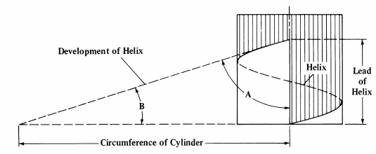
Ball and lead screws are specified by the diameter of the screw shaft and the lead (or, in some cases, pitch) of the screw thread. The lead, which specifies how far the nut travels for each revolution of the screw, is created by the thread, or helix, that wraps around the screw shaft.
If the helix is “unwrapped” from the screw, it can be used, together with the screw’s circumference and lead, to form a right triangle. The helix serves as the hypotenuse of the triangle, with the circumference and lead making up the other two sides.
In this triangle, the angle made up by the screw circumference and the helix is known as the lead angle (B). The angle formed by the lead and the helix is known as the helix angle (A). The lead angle and helix angles are complementary (their sum must equal 90 degrees), so if the lead angle gets larger, the helix angle will get smaller.
Angle A (formed by the helix and the lead) is the helix angle. Angle B (formed by the helix and the screw circumference) is the lead angle. These angles are complementary, so if one gets larger, the other must get smaller. Image credit: tools-n-gizmos.com
Note that some reference materials refer to the angle (B), between the screw circumference and the helix, as the helix angle. When the term “helix angle” is used, be sure to look for a definition or diagram to confirm which angle is being referenced.
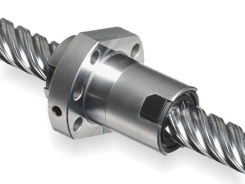
A high helix screw is generally recognized as one whose lead (P) is equal to or larger than the screw diameter (d0).
High helix screws can have a lead that’s up to 6 times the diameter of the screw. Image credit: Eichenberger Gewinde
Examples of high helix screws are sizes 20 x 20, 6 x 25, and 40 x 80, and some high helix designs have leads that are up to six times the diameter of the screw. And the larger the lead, the faster the linear travel speed. So high helix screws maximize linear travel speed while keeping the diameter, mass, and inertia of the screw small. And by keeping the rotational speed low, audible noise and vibrations are reduced.
Because the lead of a high helix screw is large — that is, the helix that wraps around the screw is “stretched out” — there are fewer effective turns of balls (in the case of a ball screw) or less screw-nut contact (in the case of a lead screw) to support the load. To counter this situation, some manufacturers add additional ball tracks, or turns, to the screw shaft — a design typically referred to as a multi-start screw. For ball screws, adding turns, or tracks, increases the number of balls available to carry the load. For lead screws, adding turns increases the amount of contact area available to carry the load — but it also increases friction and heat, which can affect the PV value of the screw.
The opposite of a high helix, or high lead, screw is a fine pitch, or fine lead, screw. Fine pitch screws are generally defined as those with a lead that’s less than one-half the screw diameter, such as a 16 x 5 or a 12 x 2 size. Fine pitch screws are typically used when very small moves are required.
Rollon has updated its SMART SYSTEM lineup of belt-driven linear actuators with a rugged new design that supports heavy loads and ensures low maintenance operation in automated manufacturing, packaging machines and food and beverage equipment.
The actuators have a self-sustaining anodized aluminum frame and a steel reinforced driving belt, and are engineered to provide stiffness for greater load capacity. Symmetrical heads on both ends of the actuators allow users to assemble the gearbox in one of four different positions. And, the SMART SYSTEM is designed to make it easy for designers to create multi-axis systems such as a two-axis Y-Z system, two parallel axis system or a three-axis X-Y-Z system using simple brackets and plates.
Rollon offers three types of SMART SYSTEM actuators to suit various motion and installation requirements. Each delivers an exceptional price-quality ratio, while their heavy-duty construction ensures high performance and keeps maintenance costs low. Designed to deliver speeds up to 5 m/sec with possible acceleration of 50 m/sec2, Rollon SMART SYSTEM actuators also achieve a high repeatability accuracy of ± 0.05 mm.
For more information about Rollon’s SMART SYSTEM belt-driven actuators, visit www.rollon.com.
igus has introduced a maintenance-free toothed belt axis specifically designed to improve sanitation in food manufacturing systems. The new drylin ZLW toothed belt axis is based on hygienic design principles and uses FDA-compliant materials.
Cleaning complex machines and systems in food production leads to longer and therefore expensive downtime. For instance, industrial bakeries are faced with the challenge of regularly cleaning huge vats and mixers, including the moving parts – the linear axes and linear slides on which the mixers are lowered into the containers. If traditional linear axes are used here, there is a high risk that flour and dough residues will be deposited in hard-to-reach places, make cleaning much more difficult and, in the worst case, introduce contamination risks.
“In order to reduce the cleaning of systems in the food industry or even in the pharmaceutical and cosmetics industries, we have now expanded our portfolio of ZLW toothed belt axes,” says Michael Hornung, igus Product Manager for drylin linear and drive technology. “The new model can be cleaned particularly quickly and thoroughly – whether with high-pressure steam jets, chemicals or simply running water. This also increases product safety.”
Designed using the guidelines of hygienic design during development, the new linear axis is easy to clean. Undercuts in the entire system are minimized where food remnants could accumulate. Likewise, there are no gaps that can occur, for example, if screw heads disappeared into a recess in order to be flush with the surface.
Equally important: rounded corners, which ensure that water can flow better during high-pressure cleaning and carry dirt particles along more easily. Water cannot collect and the formation of germs is reduced. Wherever a dead end was unavoidable, boreholes ensure that liquid drains away completely.
The igus developers use only FDA-compliant materials for the new toothed belt axis. Both the shaft end supports and linear carriages are made of corrosion-resistant stainless steel. The plain bearings, on which the carriage moves over the rail, are made of the food-grade triboplastic iglide A160, which enables low-friction dry operation without external lubricants, which could become a contamination hazard and pollute the environment.
The drylin ZLW toothed belt axis can now be ordered with a maximum stroke length of up to 3,000 mm and can optionally be equipped with a suitable stepper motor.